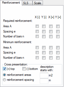
Select the Reinforcement Maps tab on the Diagrams (FEM) dialog to present maps of the required (theoretical) reinforcement obtained as a result of the deep-beam design. These are for planar finite elements.

The following values can be chosen.
- Required reinforcement of a deep beam including calculated reinforcement areas, reinforcement spacings and numbers of reinforcing bars.
- Minimum reinforcement of a deep beam including reinforcement areas and spacings as well as a number of reinforcing bars.
Individual columns denote the following reinforcement directions.
X: Horizontal.
Y: Vertical.
[+] and [-] correspond to reinforcement layers at the opposite surfaces of a deep beam. Deep-beam reinforcement is identical for both layers (symmetrical reinforcement), therefore, maps presented for both layers are identical.
Calculations of the required reinforcement area are performed by means of the analytical method assuming that they concern a structure in the Plane Stress State (compression/tension).
This tab allows reinforcement presentation in the form of crosses. Crosses for the layers [+] and [-] are identical in the case of a deep beam (symmetrical reinforcement). Cross presentation may refer to the reinforcement spacing or required reinforcement areas. Use the text fields next to the relevant fields to define start values for displaying descriptions of crosses.