Use Planar loads to define loads acting on structure bars from a load applied to a particular surface.
Planar loads are useful if you want to create the following loads:
- Ceiling beam loads caused by a load distributed over the plate.
- Loads on structure elements caused by wind acting on a curtain wall.
- Loads on structure elements because of a dead load from the roof or a wall cover.
Anisotropic surfaces
The ALPHA angle defines the possible anisotropy of the load, that is, the direction the planar load is transferred to the support bars. An example of an anisotropic surface is a corrugated plate.
The default direction of load transfer (for the ALPHA angle value = 0) is determined the same as the default setting of local coordinate systems in bars, assuming that the direction perpendicular to the load plane corresponds to the local X axis; whereas, the direction of load transfer corresponds to the local Y axis. In practice for horizontal planes, the direction of the load transfer is consistent with the global direction of the Y axis, and for other planes (vertical or inclined ones), it is horizontal. A non-zero value for the ALPHA angle causes rotation of the direction of load transfer about the line perpendicular to the plane.
Local coordinate system
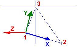
Load values can be given in the local coordinate system of a load plane. In the local coordinate system, only the pz load that is perpendicular to the plane is allowed. The local system is specified according to the positions of the 3 points that define the plane. (See the image below.)

This information provides the basis for generating a linearly distributed load on the bars participating in the transfer of a load, which constitutes a system of forces statically equivalent to the load applied to a surface.
Load application plane
Loads defined by a plane are automatically transformed into loads applied to individual bars. After these loads are generated, only the loads applied to the bars are displayed in the table (planar loads are no longer visible).
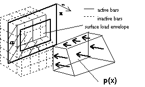
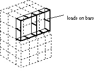
The following images show examples of a surface to which a load is applied and of loads generated on bars transferring the load from the defined plane.

