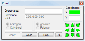
Open the Point dialog using one of the following methods:
- Click Tools menu > Point coordinates.
- Click the field displaying the cursor coordinates in the status line.
- Pressing the 0 key on the keyboard.

The dialog lets you define point coordinates relative to a selected reference point or in absolute values. Use the Coordinates field to define Cartesian or cylindrical (polar) point coordinates. This option can be used to define coordinates of nodes, bars, contours, and other objects. Note that the Reference point field displays the coordinates of the recently defined point. If a reference point is a specific point of an existing model, you can define (redefine) a node in that point.
Pressing >> expands the dialog; pressing << restores the original size of the dialog. The right of the dialog shows options for defining point coordinates or a distance from the reference point.
The bottom right corner of the dialog includes the following icons:
![]() - Defines point coordinates
- Defines point coordinates
![]() ,
, ![]() ,
, ![]() , and
, and ![]() - Determines the distance between a point being defined and the reference point in the direction of the axis of a selected plane (such as, X or Y).
- Determines the distance between a point being defined and the reference point in the direction of the axis of a selected plane (such as, X or Y).
![]() ,
, ![]() ,
, ![]() , and
, and ![]() - Determines the distance between a point being defined and the reference point in the direction of two axes of a selected plane (such as X and Y).
- Determines the distance between a point being defined and the reference point in the direction of two axes of a selected plane (such as X and Y).
Coordinates should be defined using the following format:
- Cartesian system: (x, y, z)
- Cylindrical system: (r, j, z).
The following example shows you how to use the options of this dialog when defining a structure member:
- Open the Point dialog.
- Open the Bar dialog.
- In the Bar dialog, place the cursor in the Beginning field, and next, graphically define a point being the beginning of a bar, such as a point with coordinates (1,1). Note that the coordinates of this point are entered in the Reference point field.
- Select the options: The Cartesian system and Relative coordinates.
- In the Coordinates field, enter the following coordinates: (3,2), and click Apply.
A bar is generated, the end of which, is located in the point with coordinates (4,3). In other words, a vector has been defined with respect to the reference point (the beginning of the bar) and not to the beginning of the global coordinate system.
The following image shows the differences in the operation of the Point option when relative and absolute coordinates in the Cartesian system are selected. In both cases, the point with coordinates (1,1) was the beginning of a bar; whereas, in the Coordinates field the coordinates (3,2) were entered.
|
Selected option: Relative coordinates A bar is generated: Beginning: (1,1) End: (4,3)  |
Selected option: Absolute coordinates A bar is generated: Beginning: (1,1) End: (3,2) 
|