Use this dialog to define additional parameters determining the limit displacement values according to the ANSI/AISC 360-05, ANSI/AISC 360-10, and ANSI/AISC 360-16 codes.
Access
- Click Service in the Member Definitions - Parameters dialog.
Dialog elements
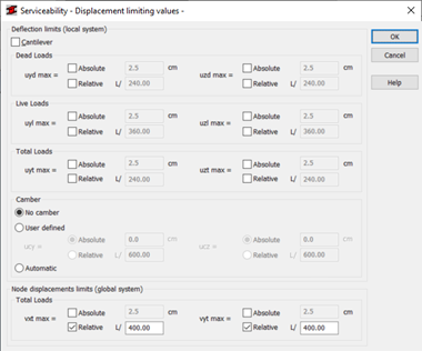
- Deflection limits (local system)
- Allows you to check displacements such as Dead loads, Live loads, or Total loads with camber for regular steel members.
Note: The program currently checks regular steel members only.
- For each of the displacements that you want to check, specify if the limiting values are relative or absolute, and then enter the member deflections in the Y and Z directions.
- Cantilever
- Specify if the member is a cantilever.
- Camber
- Contains the camber properties.
- No camber
- Select this option to ignore the camber value during the member verification or design.
- User-defined camber
- Specify the ucy and ucz values for the camber.
- Automatic camber
- Uses the camber value calculated by the program.
Note: The program uses the dead loads to calculate the automatic camber value.
- Node displacements (global system)
- Allows you to define the limits for the displacements of vertical members.
- The program checks the difference between the upper and lower displacements, and then compares it with the limit value.
- Specify the node displacements in the X and Y directions.