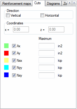
Click the Cuts tab on the Diagrams (FEM) dialog to adjust cut parameters. This tab constitutes a simplified version of the Panel cuts dialog accessible after panel calculations are performed.

The tab selects the direction of a cut (vertical or horizontal) and a value to be presented on a cut. The values available include Reinforcement in X or Y direction (horizontal and vertical) denoted Ax and Ay as well as internal forces in directions X and Y (horizontal and vertical), and also tangent lines XY denoted Nxx, Nyy and Nxy, respectively.
When a direction and value type are selected, define a point on the graphic viewer through which a cut (a diagram) will pass. Point coordinates can be manually entered.
Descriptions of extrema in cut diagrams and the other presentation options are chosen on the Diagrams tab.