This option defines rigid links in a structure. A rigid link is used to model completely rigid elements of elastic structures (definition of a rigid body in a structure). Displacements and rotations defined for a rigid link can be limited to certain selected degrees of freedom.
Basic information about defining rigid links in a structure:
- They require defining additional nodes.
- They act between the nodes. They can connect any types of finite elements (bar elements or shell elements).
- Rigid links can be used only in structures using rotational degrees of freedom.
Defining a rigid link between nodes is the same as introducing rigid compatibility conditions with respect to all displacements in these nodes. All nodes linked with a primary node constitute a group of nodes comparable to a rigid body.
For example, linear displacements can be blocked, while rotations can be allowed. The first node is the primary node, while the remaining ones are secondary nodes.
The use of rigid links can be illustrated by defining a floor which is rigid in its plane, whereas, in the direction perpendicular to the floor plane, it is pliant. A rigid link is defined as a rigid membrane linked with a primary node, to which secondary nodes with a selected set of degrees of freedom are attached. (To achieve full rigidity, all degrees of freedom for the secondary nodes should be selected.) When using rigid links, it is possible to model a membrane (see the following image) - the directions UZ RX RY RZ in the secondary nodes are released.
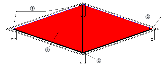
- Secondary Node 1
- Secondary Node 2
- Primary Node
- Rigid Body
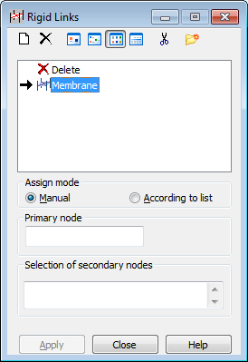
Open the Rigid Links dialog for defining the rigid links in the structure, using either method:
- Click Geometry > Additional Attributes > Rigid Links.
- Click
 .
.
The Rigid Links dialog box has the following elements:
- Field for defined rigid link types
- Primary node field, Selection of secondary nodes field for a manual definition (see the following image with 3 secondary nodes)
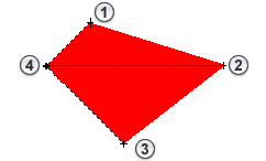
- Secondary Node 1
- Secondary Node 2
- Secondary Node 3
- Primary Node
- Primary node field and parameters (connection vector and range radius) for defining rigid links According to list (see the following image with 1 primary node and 2 secondary nodes within a defined range). All nodes in the defined range are secondary nodes of the rigid link.
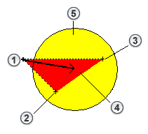
- Primary Node
- Secondary Node 1
- Secondary Node 2
- Vector
- Range
- Standard buttons (Apply, Close, Help).
At the top of the dialog are the following:
 - Defines a
New Rigid Link Definition
- Defines a
New Rigid Link Definition
 - Deletes a rigid link type from the active list.
 ,
,
 ,
,
 , and
, and
 - Displays the list of active rigid links as: large icons, small icons, a short list, or a long list.
 - Deletes from the active list all the rigid link types that are not in the structure.
 - Opens the
Label Manager dialog.
- Opens the
Label Manager dialog.
A node can be defined as a secondary node only in one rigid link. Therefore, the following notation is not correct:
1 2 3 4 LIN 10
1 6 7 LIN 9.
Similar to defining other attributes, the definition of a rigid link has 2 steps:
- Defining a rigid link type
If the active rigid link type list is empty or a new rigid link type is to be added to the active list, click New Rigid Link Definition:
- If none of the rigid link types is selected, clicking
opens the dialog for defining a new rigid link type. The fields are filled with the last rigid link definition (except for the LABEL field) or the default parameters are set.
- If a rigid link type is selected, clicking
opens the dialog to define a new rigid link type. All fields, except for Label are filled using the highlighted type.
Also, you can open the dialog for defining a new rigid link by double-clicking an element in the list of rigid links. The Rigid Link Definition dialog opens with all fields filled according to the rigid link type selected. Click Add (or press <ENTER>) to add (update) the new rigid link type to the list. If the label does not change, a warning message is displayed.
- If none of the rigid link types is selected, clicking
- Defining a rigid link in a structure.
To delete a rigid link from the structure:
- Click
 on the active rigid link list
- Select an object in the structure you want to delete the rigid link from.
You cannot modify this type of rigid link; it is assigned the same way as the rigid link properties are to a structure element.
After the new rigid link is added, its symbol displays.