In the Stories table, you can find values describing story properties and the results associated with them.
In the Stories dialog, you can select which of these properties or results are displayed in the Stories table.
- Access
-
- Click Results
 Stories to open the Stories table, and then click View Table Columns to open the Stories dialog.
 - Click Results Stories to open the Stories table, and then right-click in the Stories table and select the Table Columns from the context menu to open the Stories dialog.
Note: The content of the Stories dialog depends on which tab is selected in the Stories table (Stories, Values, Displacements, Reduced forces, Total).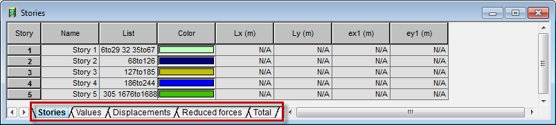
- Click Results
- Dialog elements
-
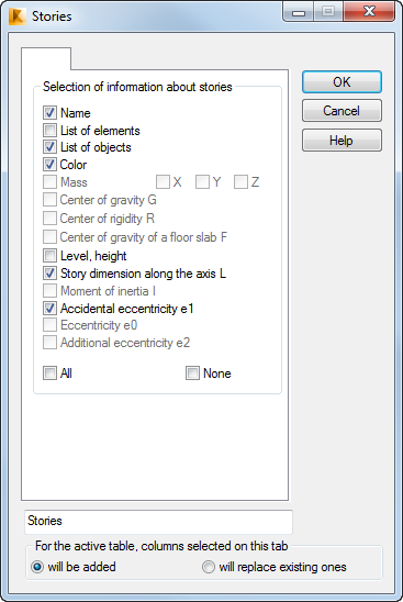
The content of the Stories dialog is common for Stories, Values, and Total tabs, but some of options are available for an appropriate tab only.
The following values are calculated for each story:
- Mass.
- G - Coordinates of the center of gravity of story (takes in consideration all the objects belonging to the story or masses added in cases of the dynamic analysis).
- R - Coordinates of the center of rigidity of the section at the height of the story's center of gravity, considering the columns, walls, and core walls.
- F - Coordinates of the center of gravity of story slab (takes in consideration all the objects located at the story slab).
- Story dimension along the axis X - Lx.
- Story dimension along the axis Y - Ly.
- Moment of inertia of the mass about the axis X - Imx.
- Moment of inertia of the mass about the axis Y - Imy.
- Moment of inertia of the mass about the axis Z - Imz.
- Accidental eccentricity along the axis X - ex1: e1 =±0,05Lx.
- Accidental eccentricity along the axis Y - ey1: e1 =±0,05Ly.
- Eccentricity ex0 - The distance between the center of rigidity and the center of gravity projected onto the X axis.
- Eccentricity ey0 - The distance between the center of rigidity and the center of gravity projected onto the Y axis.
- Additional eccentricity along the X axis - ex2 - Mass eccentricity along the X axis is applied to a given case of modal or seismic analysis when Definition of mass eccentricities is selected for the modal analysis.
- Additional eccentricity along the Y axis - ey2 - Mass eccentricity along the Y axis (as for the X axis).
The center of rigidity R is calculated for walls and columns in the horizontal section of the story. The section plane extends at the level of the center of gravity of the story, parallel to the XY plane of the global coordinate system.
The coordinates of the center of rigidity are calculated according to the formula:
RX = SUMi ( Xi * IXi) / SUMi (IXi)
where:
SUMi - Sum for i-th elements of walls or columns
Xi - Coordinate of the center of rigidity of the i element in the global system
IXi - Moment of inertia of the i-th element about its central axis (at the center of gravity) parallel to the global X axis.
The procedure is analogous for the coordinate RY = SUMi ( Yi * IYi) / SUMi (IYi)
If the walls are grouped in a core wall, the core wall section is considered as a whole. The moments of inertia for the core wall section are calculated. The coordinates of the center of rigidity for the core wall are calculated from the thin-walled member theory.
Values of accidental eccentricities e1 can be used directly as mass eccentricities in structure modal analysis. If the Definition of mass eccentricities option is selected for modal analysis, a value of the mass translation by the e2 eccentricity according to the user-defined value is assigned to each story. The mass eccentricity is considered in the modal analysis and in the seismic analysis cases that follow the modal analysis case.
Physical properties, masses, and eccentricities e0 and e1 can be helpful, if you want to construct a model for a simple seismic analysis of a structure.
- Stories tab
-
The Stories tab displays the geometrical properties of each story: list of objects and elements of a story, color, level and height, story dimensions Lx, Ly, and the values of accidental eccentricities ex1 and ey1.
- Values tab
-
On the Values tab, physical properties of each story are displayed: coordinates of the center of gravity and the center of rigidity, mass moments of inertia, as well as eccentricities e1 and additional eccentricities e2. A column containing the coordinates of the story slab center of gravity can also be added. Notice that the values of the masses are given for each case, because each case can have different added masses acting in selected directions X, Y, Z. The Masses column indicates the maximum mass of the story acting in these directions. Columns describing the values of the story mass operating in every X, Y and Z direction may also be added.
- Displacements tab
-
The Displacements tab displays the maximum values of nodal displacements projected to the X and Y axes as well as values of drifts dr Ux, dr UY.
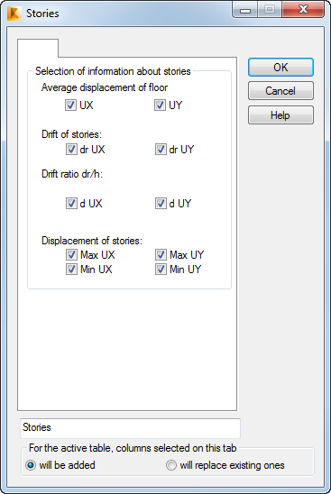
The drift of stories is calculated as the difference of the average displacement of the gravity center of a story slab of the subsequent stories. As in the story slab gravity center calculation, the average displacement of the story slab gravity center is weighed by the weight of the slab objects. As an example, the averaged displacement in the X direction, UXF = SUM(i) (UXi * Wi) / SUM(i) Wi, where the UXi is the displacement of the UX gravity center of the i-finite element, the Wi weight of a finite element.
The drift ratio d = dr / h is also presented in the table, where h stands for the story height.
- Reduced forces tab
-
The Reduced forces tab displays forces in a section through a story (a cut through panels and members) reduced to the center of gravity.

Results are displayed by load cases and successive stories (first column). The next columns show the following information:
- Coordinates of the center of gravity for a story,
- Values of reduced forces for a story,
- Value of forces per columns (members) and walls (panels) on a story,
- Values of the alpha cr factor along X, Y directions. The alpha cr is the factor by which the design loading would have to be increased to cause elastic instability in a global mode. Note: Alpha cr X and alpha cr Y columns are available if Global mode elastic instability multipliers alpha cr along X, Y directions option is selected.
Total reduced forces for a story are calculated based on external loads applied to nodes of the story. If loads are applied to objects such as columns or walls, Robot considers forces distributed to nodes of a member or to nodes of a finite element mesh of a panel. As a result, loads applied to nodes at the lower level of the story are ignored in the sum of forces for a story.
Nodal loads are reduced to the center of gravity of a story. Thus, forces and equivalent moments in the 3 directions: X, Y, and Z are obtained.
Reduced forces per columns on a story are calculated based on internal forces in the member cross-section. The cut is parallel to the XY plane of the global coordinate system at the level of the bottom of a story. As a result of the reduction, a set of 3 forces and 3 moments reduced to the center of gravity is obtained.
Reduced forces per walls on a story are calculated as a difference between the total reduced force for a story and the reduced force for columns.
The following rules apply to a seismic case with a number of modes and their combinations (CQC or SRSS):
- Reduced forces for a whole story, and for columns are calculated separately for each mode.
- The reduced results for modes are combined into mode combinations for a whole story and for columns.
- The value of a reduced force for walls in the mode combinations is calculated as a difference between the combined results for a whole story and the combined results for columns.
- Total tab
-
The Total tab on the Stories table, displays physical properties of a whole model: coordinates of the center of gravity and mass moments of inertia for the entire structure. Depending on the participating added masses, these values might change for successive cases. If no stories are defined in a model, the mass eccentricity e2 from modal analysis is assumed for the whole building.
See also: