Use the options on this tab to define the basic information on the geometry of the bracings.
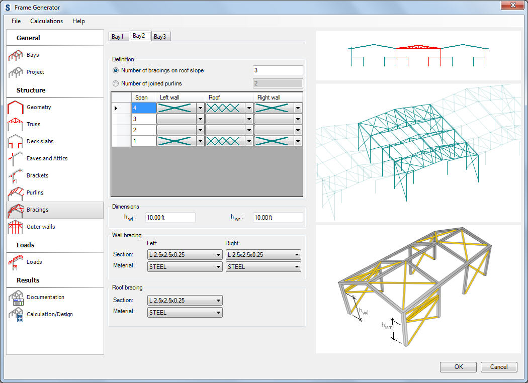
Data to define bracings for a selected bay:
- bracing definition method:
The number of bracings on the roof side
The number of connected purlins - the definition of how many purlins are contained in a bracing field (default number = 2, i.e. the bracing is inserted between two purlins)
- the table presenting the bracing layout in a bay for the particular spans (the roof bracings and the wall bracings)
The bracings can be defined in a arbitrary span (the space between the subsequent frames) of a bay; to define the wall bracing type, select a bracing type from the selection list located in the Left wall or the Right wall column; the roof bracing type should be selected from the selection list in the Roof column.
Moreover, the height of the element of the transverse bracing should be defined (if exists) on the right and the left wall.
The section and the material of the roof and wall bracing bars should be defined in the bottom part of the dialog. Select the More option in the selection list of profiles to open an additional dialog where you can add another profile from the selected profile database to the list of the available profiles.