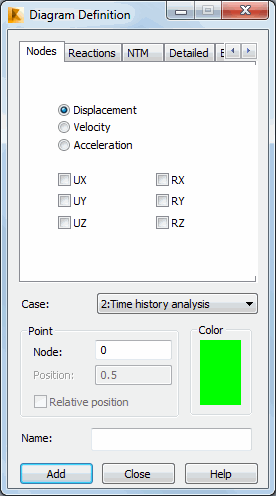
The Diagram definition dialog defines diagrams of quantities calculated during the time history analysis. Open it clicking Add or Modify in the Time history analysis dialog.

A diagram is created for the selected, single resultant quantity. The quantity must be selected in one of the available tabs in the dialog (note: the number of available tabs depends on the type of analyzed structure, such as frame, plate). Additionally, you must specify an element (bar) or node for which to prepare a diagram. When you select quantities for bar elements, thePositionfield is available to specify a relative coordinate along the bar length for which the desired results are saved. Forsurface elements, values of forces and stresses are read at centers of elements.
The Case list lists of defined time history analysis cases. A function diagram is saved for a specified case.
The name of function diagram is created automatically:
(case_number)_(quantity_name)_(option_name)_(element_or_node_number)/(position_along_bar).
You can change a diagram name. You cannot define a function diagram if you have not selected any quantity from the Diagram Definition dialog, or if you have not defined a diagram name.
The dialog in the previous image is for bar structures.For shell structures, it has more tabs (such asDetailed, Complex, and so on).
As an example, create a diagram for structure nodes on the Nodes tab. Options in the dialog differ depending on whether you selected Displacement, Velocity or Acceleration:
- for Displacements:displacements and rotationsUX, UY, UZ, RX, RY and RZ,
- for Velocity: displacement velocities VX, VY, VZ, and rotations RX, RY, RZ,
- for Acceleration: displacement acceleration AX, AY, AZ, and rotations RX, RY, RZ.
To create a diagram for the UZ displacement, you must:
- select Displacements
- select UZ
- select a time history analysis case
- select a node for which the diagram is prepared
- select a diagram color (clic the color in the Color field)
- specify the diagram name or accept the default one.
You can define function diagrams for other quantities in the same way as specified previously. Onthe Reactions tab you can select values of reactions at a selected support node.