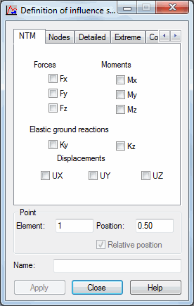
The Definition of influence surface dialog shown in the following image opens after clicking Add or Modify in the Load Pattern dialog.
Influence surfaces are defined identically as influence lines for the analysis of moving loads. The difference consists only in that a user defines a function and assigns a name to it.
Both influence lines and surfaces are diagrams of a relationship between a certain result value (such as, force or displacement) and the position of a unit force. The value of an influence line at a given point is equal to the value of a selected result quantity when a unit force is positioned at this point.
Influence surfaces in Robot are generated using the static method. It means that they are generated by applying a concentrated unit load at successive points. After all the unit cases are solved, an influence surface taking results from successive cases is constructed. When applying influence surfaces, you should remember 2 important points about how they are generated:
- The accuracy of the influence surface mapping depends on the density of the division applied to the surface defined as a deck. Unit forces used to construct an influence surface are applied at nodes belonging to the mesh of this surface division. The density of the mesh division is defined the same way as finite element meshes, using the Tools > Job Preferences > Meshing Options option. This option is available, as well, after highlighting the surface contour and selecting the Object Properties option from the context menu.
- Influence areas are generated for a unit load that operates in the direction of the Z axis (sense: Z minus). The values of the influence surface are generated with signs compatible with the results of this load. For some of the quantities, such as, displacements or moments on supports, the maximum values on the influence surface can be negative. You should select which of the influence surface parts, positive or negative, will be loaded and unloaded.

A function is defined after selecting only 1 result quantity on any of the tabs and selecting an element or node. For bar structures, the Position field is also available, which lets you determine a relative coordinate on a bar for which results are saved. For surface elements, the values of forces and stresses are read at element centers.
If you do not specify a function name, the name is generated automatically in the following manner: (result_quantity_name)_(quantity_type)_(number_of element_or_node)/(position_on_a bar), such as, Displacements_UX_1/0.5.
If none of the values in the dialog is selected or there is no name for the influence surface, then you cannot define a function.
Clicking Apply button completes the definition of an influence surface and adds the surface to the influence surface list.
In the Definition of influence surface dialog, you can select the following result quantities on the successive tabs:
- NTM (forces, moments, elastic ground reactions, displacements)
- Nodes (displacements, reactions)
- Detailed (results for surface elements with a selected direction of the local system)
- Extreme (results for surface elements in the principal system)
- Complex (results for surface elements composed according to the von Mises hypothesis)