Using this option, you can define panels within structures. Access the option by:
- Clicking Geometry menu > Panels.
- On the Structure Definition toolbar, clicking
 .
.
After the option is selected, the Panel dialog displays.
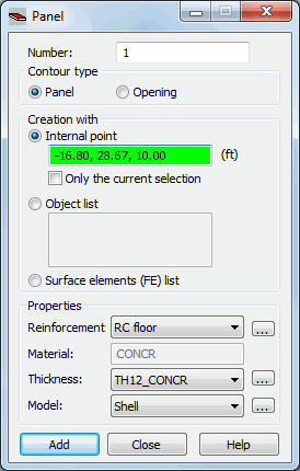
To define a panel, specify its parameters:
- Number
- Contour Type
- Panel
- Opening
- Face (option available only in Volumetric Structure Design)
If Face is selected for Contour Type, all options under Properties become unavailable. Selecting this option causes the object that is being generated to be defined as a face (without assigning properties such as reinforcement type and thickness). Such an object can be used during generation of a volumetric structure (solid) and it may constitute a face of such a volumetric object.
- Creation With
- Internal Point
- Object List
- Surface Elements (FE) List
- Properties
- Reinforcement - type of reinforcement for the panel
- Material - this is a read-only field; it displays the material defined for the selected panel thickness.
- Thickness
- Panel calculation model.
 to the right of Reinforcement, Thickness and Model, you can access the New Bar Type, New Section or Panel Calculation Model dialog, in which you define a new panel thickness, plate and shell reinforcement type or panel calculation model. The defined thickness, reinforcement or model types are then added to the appropriate lists of thickness, plate and shell reinforcement types or panel calculation models.
 The extents of the panels are defined by defining their edges (definition of contours). The panel contour may contain bar elements, objects, and polylines. To define a panel:
- Indicate a point within the panel (coordinates of a point located within the contour).
- Provide the number(s) of objects comprising the contour.
- Provide numbers of the generated planar finite elements. The option may be used after a mesh of finite elements is generated (by clicking Analysis menu > Calculation model > Generation). This option is useful when it becomes necessary to change properties of a part of a generated panel (for example, to change the thickness in the near-opening zone or at the edges).
After panels are defined and calculations started, a planar FE mesh is created according to the parameters you specify in the Job Preferences dialog (Meshing Options).
The FE mesh is visible only after the FE Mesh option is selected in the Display dialog.
For a given contour, you can repeat the procedure for creating an element mesh. However, the "new" planar element mesh will overwrite the existing one. Two planar FE types are available in the software:
- triangular elements (3- or 6-node)
- quadrilateral elements (4- or 8-node).
During FE mesh creation, the nodes inside the selected area are created first, and then the nodes are assigned to the appropriate finite elements. Nodes inside the area (contour) may be created using an algorithm:
See also:
Examples of creating finite element meshes (plates and shells)