Use this option to define code parameters of a member type for the German DIN code. There are two ways to access this option:
- Click the New member type option in the Member Type dialog
- Click the Parameters button in the Definitions dialog dialog.
The following dialog displays:
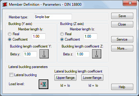
The Member Type field displays the name of the selected member type (enter the name of the defined bar type). The Buckling with respect to axis Y and Z fields displays the length of a member for the appropriate plane. There are two ways to define this length:
- Select the Real option, the introduced value is interpreted directly as member length
- Select the Coefficient option, the introduced value is interpreted as the coefficient by which the real member length should be multiplied to obtain the required value. For instance, if one introduces the value 0.25, it means that the relevant member length equals 1/4 of the real length.
Choose the Coefficient option to define at a time several members of different actual lengths, with additional supports equally spaced, for example. Also, use the Coefficient option, if the set parameters are to be saved as a category. Entering a value of 1.0 will guarantee that each member (defined using the category as Ly) will have its actual length accepted.
The Member buckling length coefficients in both directions (Beta y and Beta z) are described in the Buckling Length Coefficient dialog. The actual bar length (or the sum of the component member lengths) is entered automatically in the appropriate fields.
The Buckling length coefficient depends on the end-support condition of the bar nodes in the buckling plane. The Buckling length is also be defined in the Buckling Diagrams dialog, opened by clicking the icon representing the selected buckling model type. After selecting a typical scheme, the coefficient value will be accepted or calculated automatically.
The icons in the dialog box are divided into two groups:
- The first group contains typical (code) methods of member support and corresponding values of buckling coefficients.
- The second group contains icons of options used for calculating buckling coefficient for columns of multi-story frames.
Buckling is always considered in calculations if a compression force appears in the member, even if it is negligible in comparison to the other internal forces. A separate analysis is not performed that would determine if buckling effects should be disregarded. To eliminate buckling effects from the calculations, the last icon must be chosen. If selected, buckling will be disregarded in the calculation process.
In the Lateral Buckling Parameter field select options used during the verification of the lateral buckling for the member: lateral buckling type, load level and the lateral buckling length coefficient. Selecting the appropriate icon opens the dialog for the definitions for corresponding parameters.
It is necessary to include the level of load application as well, in order to describe lateral buckling conditions. The ordinate height of load application is defined in the member section axis system. Assuming that lateral buckling occurs when loading the member in the XZ plane, only one coordinate is entered. It is a relative value from the <-1.0,1.0> interval. If the load is applied at a characteristic section point - upper flange, lower, etc. then, the coordinate value will be entered automatically once an appropriate icon is chosen.
Lateral buckling calculations requires you to provide the distance between sections blocked against twisting for each bar (lateral buckling length). It is necessary to distinguish two buckling lengths (for the upper and for the lower flange) as it is possible to attach the upper and lower flanges separately, which results in the appearance of different load cases of compression forces. You should provide the value of the coefficient by which the base bar length is multiplied to obtain the lateral buckling length. The length IZ is taken as the base length. The coefficient value is entered directly or by selecting the icon representing typical attachment case for which the coefficient will be automatically chosen.
Click the More button to open an additional dialog. You can then define the remaining bar type parameters described in the code as: Anet/Agross ratio.
Click the Service button to open an additional dialog. You can then define the parameters of bar type (limit displacements, initial deflection).
Click the Save button to save the bar type with a defined name and parameters to the list of previously defined steel member types.