The option enables detailed analysis of timber members. The detailed analysis of a member can be launched by pressing the Detailed button in the dialog box with detailed results for the NF EN 1995-1:2005/NA:2010/A2:2014 code.
The program makes it possible to run additional calculations based on the requirements described in the code NF EN 1995-1:2005/NA:2010/A2:2014:
- beam strength for compression perpendicular to the grain at the support (chapter 6.1.5)
- shear strength of a beam with holes (chapter 6.6)
- shear strength of a beam with a notch at the support (chapter 6.5.2).
Each of the member analyses listed is performed independently, thus each of them can be launched separately. To start definition of calculation parameters and calculations, the user should activate the Consider in calculations option in the upper part of the dialog box on each tab.
The dialog box consists of three tabs:
Transversal compression
Openings
Cuts.
The Transversal compression tab (chapter 6.1.5)
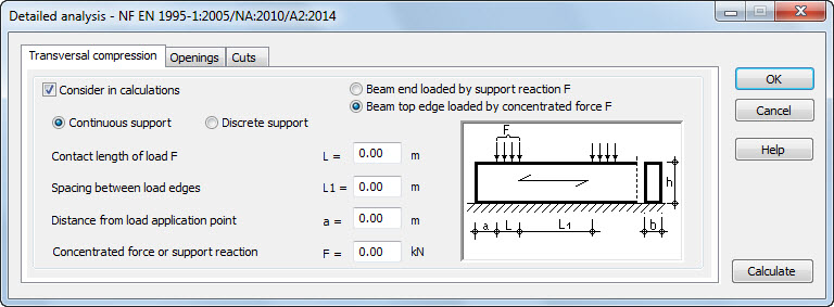
The options provided on this tab are used to verify the strength for compression perpendicular to the grain of a beam subjected to action of a compressive force F applied to the top or bottom edge of a beam.
Selection of the Beam end loaded by support reaction F option makes available definition of the parameters (L, a, F) which are necessary to determine the factor kc,90 according to point 6.1.5.(3). It has been assumed that the beam end is loaded by the support reaction of F value, acting on the bottom edge of the beam. Moreover, another assumption has been adopted, that the support positioned at the distance of a ≤ h/3 is treated as an outermost support (if this not the case, calculations are performed as for an internal support).
Selection of the Beam top edge loaded by concentrated force F option makes available definition of the parameters (L, L1, a, Ls, as, F) which are necessary to determine the factor kc,90 according to point:
- 6.1.5.(5), if the height-to-width ratio of the beam h/b ≤ 2.5
- 6.1.5.(6), if the height-to-width ratio of the beam h/b > 2.5.
The program determines appropriate effective lengths of load distribution as shown in figures 6.3 and 6.4. It is also possible to choose the method of beam support by selecting one of the following options: Continuous support or Discrete support.
The Openings tab (chapter 6.6)

The options provided on this tab are intended for verification of shear strength of a beam with holes. The verification is carried out for all holes defined by the user. The program reads automatically values of transversal forces acting at points where holes are positioned for a decisive load case. Before starting the calculations, it is checked whether defined holes are geometrically correct and if an error occurs, the relevant warning appears.
There are two types of holes available: Round holes or Rectangular holes (a hole type may be selected in the upper part of the dialog box).
However, it should be remembered that a number of coordinates of hole center positions must agree with a number of diameters/widths and a number of heights (for rectangular holes).
The Cuts tab (chapter 6.5.2)
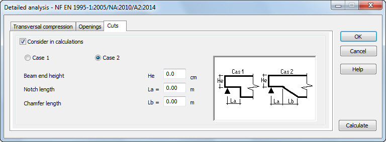
The options provided on this tab are used for verification of shear strength of a beam with a notch at the support. The verification is carried out for one of the beam ends at the point where a larger shear force is acting. The program reads automatically values of shear forces acting on beam ends for a decisive load case.
It is possible to define two cases of a beam notch: Case 1 or Case 2.
Each of the tabs holds the Consider in calculations option. If this option is inactive, then an analysis of e.g. compression perpendicular to the grain will not be carried out and none of the options on this particular tab will be accessible. If the Consider in calculations option is activated on any of the tabs, then an analysis of e.g. compression perpendicular to the grain will be performed after defining several parameters.
After defining parameters available in the dialog box and pressing the Calculate button, an additional analysis of timber members is carried out. Once it is completed, the program runs a calculation note containing results of the calculations performed.