The option is used to define the buckling length of members. It is available after pressing the relevant icon (for the direction Y or Z) in the Buckling length coefficient field in the Member definition - parameters dialog box.
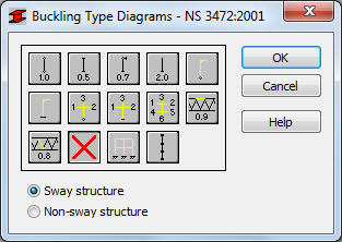
The buckling length coefficient is entered automatically once one of the icons with the appropriate end support conditions is selected. The icons are divided into two groups: the first one contains typical (code) methods of member support and corresponding values of buckling coefficients, whereas the other contains icons of options used for calculating the buckling coefficient for columns of multi-story frames (calculation of the buckling length coefficient for one, three and six adjoining bars). Double-clicking one of the icons symbolizing calculation of the buckling length coefficient (![]() ,
, ![]() ,
, ![]() ) results in opening an additional dialog box.
) results in opening an additional dialog box.
Buckling is considered in calculations always when a compression force appears in the member, even if it is negligible in comparison to other internal forces. The program does not perform on its own a separate analysis that would determine if buckling effects may be disregarded or not. If the user wants to eliminate buckling effects from the calculations, the ![]() icon has to be chosen. If pressed, buckling will be disregarded in the calculation process.
icon has to be chosen. If pressed, buckling will be disregarded in the calculation process.
The last icon ![]() enables members with internal bracings (lateral stiffeners of the analyzed members limiting the buckling length) to be considered in calculations. After double-clicking this icon, the screen shows the Internal bracings dialog box where parameters of lateral stiffeners may be determined.
enables members with internal bracings (lateral stiffeners of the analyzed members limiting the buckling length) to be considered in calculations. After double-clicking this icon, the screen shows the Internal bracings dialog box where parameters of lateral stiffeners may be determined.