Use the Face Manager to edit the UV grids of a divided surface in the conceptual design environment.
Select a surface and click the Face Manager icon at the center of the 3D Control to open the Face Manager. 

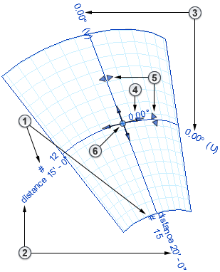
The UV grid editing tools display on the divided surface. Note that the controls allow you to modify UV grids independently of one another. 


|
Fixed Number | Click the number value in the drawing area and enter a new quantity. |

|
Fixed Distance | Click the distance value in the drawing area and enter a new distance. Note: The Distance drop-down list on the Options Bar also allows for a minimum or maximum distance, rather than an absolute distance. This option is only available when the surface is initially selected (not in the Face Manager).
|

|
Grid Rotation | Click the rotation value in the drawing area and enter a new angle for either grid. |

|
All Grid Rotation | Click the rotation value in the drawing area and enter a new angle to rotate both grids equally. |

|
Belt Measurement | Click and drag these controls to reposition the belts along their respective grids. Each belt represents the line along the surface from which the chord distance between grids is measured. The distances can be proportionately different along a curved line. |

|
Justification | Click, drag, and snap this widget to a surface edge (or center) to justify the UV Grid. The new location is the origin for the UV Grids layout. The Align tool can also be used to align a grid to an edge. |
Each of these parameters can be specified in the Options Bar or Properties palette.