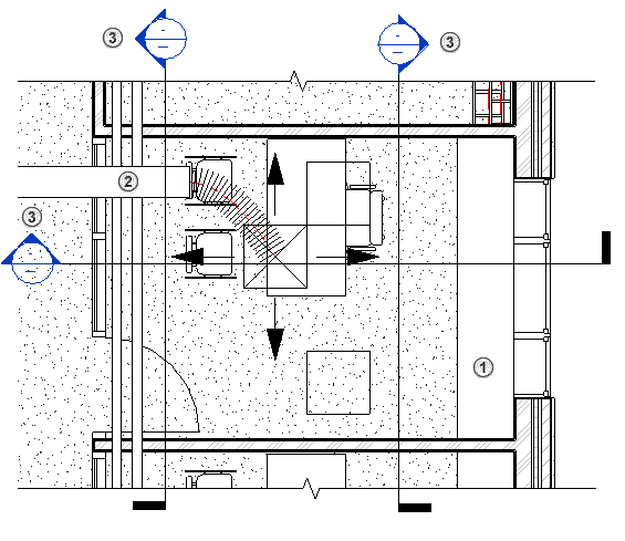
The Discipline property determines how discipline-specific elements display in a view.
Use the Discipline property to control the following behaviors:
- Which element categories display in the view, based on their related disciplines
- Which view tags display in the view
- Whether the view range and its cut plane control the display of elements in plan views
- Whether automatic hidden lines are applied to the view
The Discipline property affects views whether you are using a single model that incorporates multiple disciplines, or the model links to other discipline-specific models.
You can also use this property to organize views in the Project Browser. See Organizing Views in the Project Browser.
To set the Discipline property for a view, select the view name in the Project Browser, or open the view. On the Properties palette, the Discipline property is listed in the Graphics section. Select a value from the list.
The examples below are based on a model in which the following is a Level 1 section plan. In the section plan, the green arrow indicates the entire view range for corresponding plan views. The blue arrow indicates the primary view range, which has been extended above the ceiling into the plenum, and below Level 1. The orange arrow indicates the view depth. (See About the View Range.) In the sample plan views below, the Detail Level is set to Fine so that mechanical, electrical, and piping elements display more fully for illustration purposes.
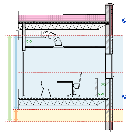
If desired, you can download the model to better understand how the Discipline property affects views: view_discipline_example.rvt
Views Inherit the Discipline of the Originating View
When you create a view based on an existing view, the new view inherits the discipline of the originating view. This rule applies to callouts, sections, elevations, and duplicate views.
For example, suppose you open a structural plan view (a plan view whose Discipline property is set to Structural), and you use the Section tool to create a section of the plan view. The Discipline property of the new section view is also set to Structural.
View tags (the symbols used to indicate sections, elevations, and callouts) display in a view only if the discipline of the current view matches the discipline of the target views. See the examples below.
Architectural Discipline
When the Discipline property is set to Architectural:
- All element categories display in the view, regardless of their related disciplines.
For example, the view displays architectural columns and structural columns, as well as mechanical, electrical, and piping elements.
- In plan views, the view range and its cut plane control the display of elements in the view.
- Plan views display view tags only for architectural callouts, sections, and elevations.
- When the Show Hidden Lines view property is set to By Discipline (the default), automatic hidden lines do not display.
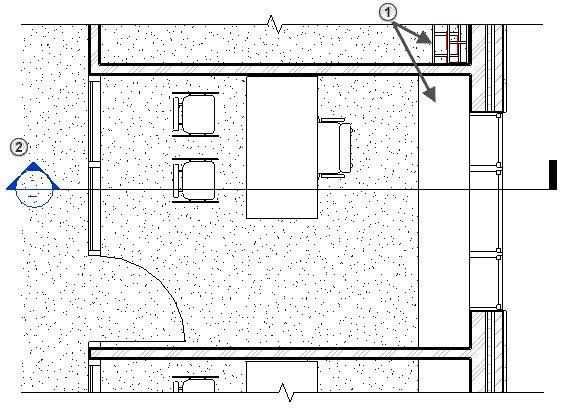
Examples: In the following architectural floor plan:
 On one side of the wall, cable trays are exposed. On the other side of the wall, the cable trays are obscured by an architectural cover.
 A tag displays for a section view whose
Discipline property is set to
Architectural. The plan does not display tags for views assigned to other disciplines.
Structural Discipline
When the Discipline property is set to Structural:
- All element categories display in the view, regardless of their related disciplines. However, non-structural walls are hidden.
For example, the view displays architectural columns and structural columns, as well as mechanical, electrical, and piping elements.
- In plan views, the view range and its cut plane control the display of elements in the view.
- Plan views display view tags only for structural callouts, sections, and elevations.
- When the Show Hidden Lines view property is set to By Discipline (the default), automatic hidden lines display in the view.
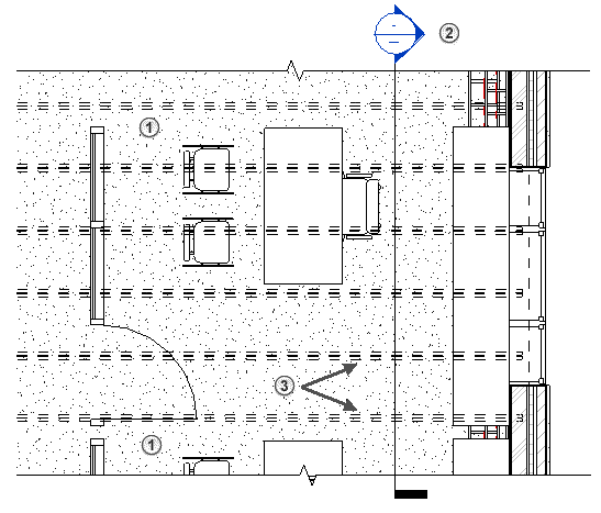
Examples: In the following structural plan view:
 Non-structural walls do not display. (Compare with the architectural plan shown above.)
 A tag displays for a section view whose
Discipline property is set to
Structural. The plan does not display tags for views assigned to other disciplines.
 Hidden lines display to show structural framing elements below the floor because the plan's view range extends below Level 1.
Mechanical, Electrical, and Plumbing Disciplines
When the Discipline property is set to Mechanical, Electrical, or Plumbing:
- Elements from the mechanical, electrical, and piping categories display in the view according to their settings in Object Styles.
- Ceiling elements do not display in plan views.
- All other categories display using halftone. To select these halftone elements, you cannot use a selection box. Instead, select each halftone element individually.
- In floor plan views and callout views, most mechanical, electrical, and piping elements within the view range are drawn on top of other elements regardless of whether the cut plane intersects them. Plumbing fixtures, however, do not overlay other elements in this way.
- Plan views display view tags only for callouts, sections, and elevations with matching disciplines.
- Hidden lines for elements are controlled as follows:
- For mechanical, electrical, and piping elements, hidden lines display in the view based on the Show Hidden Lines view property and additional settings on the Hidden Line pane of the Mechanical Settings dialog and the Electrical Settings dialog.
- For elements of all other categories, hidden lines do not display. For these elements, the ribbon disables the Show Hidden Lines and Remove Hidden Lines tools.
- Inside Gap and Outside Gap (halo) settings for mechanical, electrical, and piping elements are defined using the Hidden Line pane of the Mechanical Settings dialog and the Electrical Settings dialog.
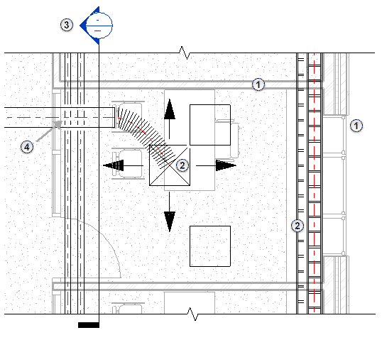
Examples: In the following mechanical plan view:
 Architectural and structural elements (walls, doors, windows, furniture) display in halftone based on the view range. Ceiling elements do not display in the view.
 Mechanical, electrical, and piping elements display as defined by Object Styles. These elements overlay other elements, regardless of their actual vertical location in the model.
 A tag displays for a section view whose
Discipline property is set to
Mechanical. The plan does not display tags for views assigned to other disciplines.
 Hidden lines for mechanical, electrical, and piping elements display in the view.
Coordination Discipline
When the Discipline property is set to Coordination:
- All element categories display in the view, regardless of their related disciplines.
For example, the view displays architectural columns and structural columns, as well as mechanical, electrical, and piping elements.
- In plan views, the view range and its cut plane control the display of most elements in the view.
Some mechanical, electrical, and piping elements within the view range display regardless of whether the cut plane intersects them.
Furthermore, mechanical, electrical, and piping elements that are above the cut plane are drawn on top of other elements. Among these elements, their draw order is defined by relative heights from the view's level. When these elements occur below the cut plane, they are drawn in order with respect to the distance from the cut plane.
- Plan views display view tags for callouts, sections, and elevations for all disciplines.
- When the Show Hidden Lines view property is set to By Discipline (the default), automatic hidden lines do not display.
Examples: In the following coordination plan view:
 Elements of all disciplines display in the view according to the view range.
 Mechanical, electrical, and piping elements display, overlaying other elements according to the rules described above.
 Tags display for section views for all disciplines.
