You can customize the appearance of panel schedules. You can specify settings for general appearance, as well as circuit information and the loads summary.
- Click Manage tab
 Panel Schedule Templates
  Edit a Template.
- In the Edit a Template dialog, for Templates, specify a template, and click Open.
- On the Modify Panel Schedule Template tab, click Set Template Options.
- Set template options in the following categories as needed:
General Settings
- In the left pane, select General Settings.
- For Total Width, specify the width of the plotted schedule in inches.
- For Number of slots shown, specify whether the slots to display are determined from the electrical equipment or set a constant value. If you select Variable based on maximum number of single pole breakers, the number of slots is determined by the Max Number of Single Pole Breakers parameter in the electrical equipment properties.
Note: If the number of poles on a device exceeds the number of slots specified for by the template, a warning displays.
- For Show in panel schedule, specify whether to display the Header, Loads Summary, and Footer parts of the template.
- For Borders, specify whether to display an outside border and a border between parts of the template.
The General Settings options allow you to customize the overall panel schedule appearance such as the width, parts, borders, and number of slots and parts that are shown. You can modify these settings before or after creating a panel schedule to make it comply to your specifications.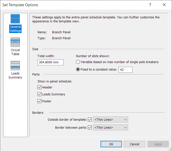
Circuit Table
- In the left pane, select Circuit Table.
- Specify column header text orientation. The selected format for displaying loads provides an interactive way to customize the format of the loads table.
- Specify a format for displaying loads. The formatting options are dependent on the panel schedule template type (and panel configuration) that you are editing. The panel configuration determines the available formatting options.
- Specify the unit of measure on phase columns.
- Specify whether to show the circuit number on one row for multi-phase circuits.
- Specify whether to display multiple rows for multi-phase circuits.
- Specify auto-shading for displaying load. When automatic shading is enable, it has the following effects:
- In 1- or 2- pole panels, the cells in visible columns related to unused phases are shaded. Under For panels other than three phase, select, Show but disable column for unused phases.
- In schedules that have their size fixed to a constant value under General Settings > Size, shading is applied to cells in rows greater than the panel's Max Number of Single Pole Breakers parameter value.
- In cells that don't represent a valid load value location, shading is applied.
Note: This option is available where the Part Type = Panelboard, and the Panel Configuration = Two Columns, Circuits Across or Two Columns, or Circuits Across. - Specify whether to show phase column values in Apparent Load (VA) or Current (amps).
Specifies the layout of the panel schedule circuit information, and circuit related settings.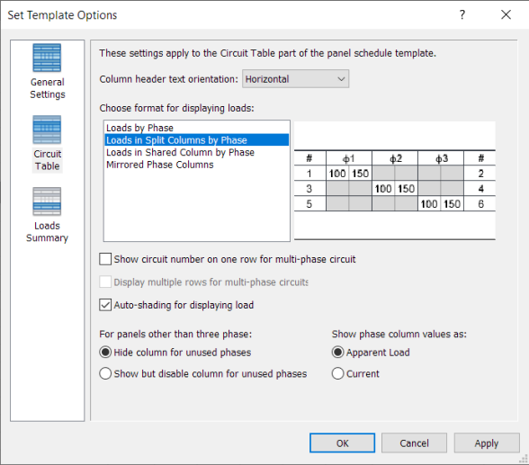
Loads Summary
- In the left pane, select Loads Summary.
- For Column header text orientation, specify how the text displays.
- For Show in panel schedule, specify whether to display only connected loads or a constant set of loads. When you select a constant set, use the Add and Remove buttons to specify the loads to display.
Specifies which load classes to display in the panel schedules, and specifies their ordering.
Loads summary options