You can create electrical systems that connect similar data, telephone, or fire alarm components.
Revit does not check voltages or the number of poles for connectors in these types of circuits.
Select a panel for the data circuit
- Select one or more data, telephone, or fire alarm devices.
- Click Modify | Data Devices tab
 Create Systems panel
 Data.
Data.
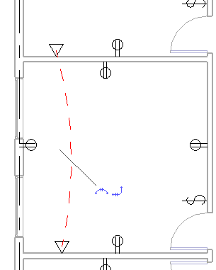
The circuit that is created displays as dashed lines between the selected devices.
Two controls associated with the circuit allow you to automatically create Create Permanent Wiring for the circuit. Adding wiring to your project is optional. Logical circuits maintain the information associated with them without adding permanent wiring. You can use circuit properties to specify the type of wire used in a circuit.
- ClickModify | Electrical Circuits tabSystem Tools panel
 Select Panel.
- Select a panel in the view.
Note: Panel families to be used for data, telephone, and fire alarm circuits should be in the Electrical Equipment category, assigned a Part Type of Other Panel, and need to have a single connector of the desired type of circuit. For example, a network switch family will need to have a Data connector in order to connect circuits from data outlets to the network switch.
- Click Modify.
Dashed lines show a temporary representation of the wiring. The receptacle connectors change color from green to blue to indicate that the logical circuit has been created.