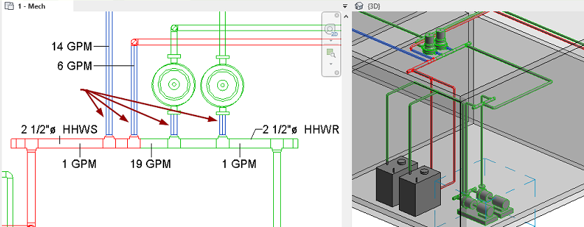
Separate hydronic piping networks into loops to calculate the flow and pressure loss for each loop.
To add hydraulic separation
- Select either the start or end pipe (or both) for the secondary loop.
Tip: You can select more than one pair of pipes.
- Click Modify | Pipes tab
 Hydraulic Separation panel
 (Add Separation).
A graphic appears on the end of the pipe at the separation point as shown below.
Tip: To control the visibility of the hydronic separation symbol, click View tab Graphics panel
 (Visibility & Graphics). On the Model Categories tab, expand the Pipes category to enable/disable Hydraulic Separation Symbols.
Graphics panel
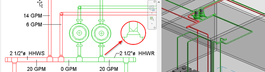
When a tap is used, the exact point of separation is located between the tap and the main or header. When a tee is used, the exact point of separation is between the tee and the branch pipe or any fitting connected to the tee. The common pipe, the pipe between the secondary supply and return junctions on the header, displays a flow of zero.
The read-only parameter, Loop Boundary, indicates whether the selected pipe is a boundary for separated loop.
To remove hydraulic separation
- Select one or more loop boundary pipes in a child loop.
- Click Modify | Pipes tab Hydraulic Separation panel
 (Remove Separation).