This method places a space where its volume is constrained from a base level to a level above in which the space spans multiple levels. You use this topic when placing spaces in shafts and chases, or in other areas that span multiple levels.
For placing spaces that do not span multiple levels, see Placing Spaces.
In the Project Browser, open a floor plan that contains the area where you want to place a space.
Next, you create a section view to verify the space vertically.
Create a section view
- Click View tab
 Create panel
 (Section).
You can use an existing section view but make certain that the section line intersects the area in which you are placing the space.
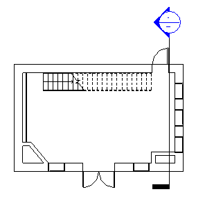
Note: In the following examples, only one section view was needed because each level consists of a single space. You may need additional section views depending on the complexity of your design. - In the floor plan, draw a section.
Make certain that the section line intersects the area in which you are placing the space. If not, the space will not display in the section view.
- In the Project Browser, double-click the new section view to open it.
Create levels
- Click Systems tabDatum panel
 (Level).
- In the Type Selector, select the level type.
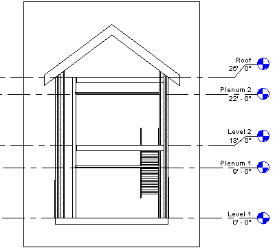
- In the drawing area, place levels in the building model, including a level at the top of the shaft.
- Click Modify.
If your project contains levels including a level at the top of the shaft, you can skip this section.
Activate spaces visibility
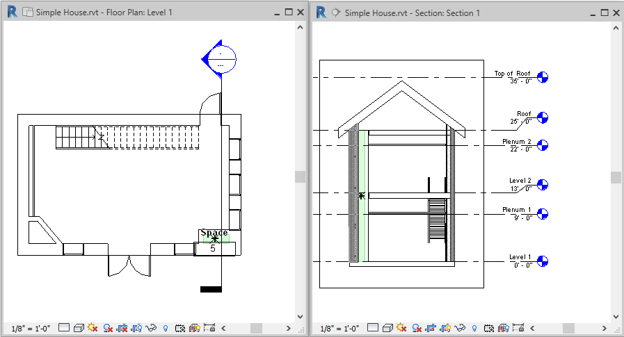
- Close all views, except the section view and the floor plan where you want to place the space, and type
w t on the keyboard to tile the 2 views.
You can also click View tab
Windows panel (Tile Views).
- Click in the section view to make it active, and type v g on the keyboard.
- On the Model Categories tab of the Visibility Graphics dialog, scroll down to Spaces.
- Expand Spaces, select Interior and Reference (if you want to display reference crosshairs), and click OK.
- Repeat to make spaces visible in the floor plan view.
Place a space
- With the floor plan view active, click Analyze tabSpaces and Zones panel
 (Space).
Note: You may need to load space tags in the project, if they are not already loaded.
(Space).
Note: You may need to load space tags in the project, if they are not already loaded. - On the Options Bar, do the following:
- For Upper Limit, specify the level at the top of the shaft.
- For Offset, enter
0' 0" (0.00 mm).
These 2 options specify the vertical extent or height of the space.
- In the Space box, either verify that New is selected if placing a new space, or select an unplaced space from the list to place it.
- Tag on placement: Places a space tag upon placement of the space.
Tag on placement is selected by default. If Tag on placement is selected, you can select the tag type from the Type Selector.
- Tag location box: specifies either Horizontal, Vertical, or Model as the space tag location.
Applicable only if Tag on placement is selected.
- Leader: Creates a leader line for the space tag.
Applicable only if Tag on placement is selected.
- Show Bounding Elements: Highlights the room-bounding elements in the building model for immediate recognition.
Select the following options as needed:
- In the floor plan view, move the cursor over the shaft area in the building model, and click to place a space.
Note: Spaces can only be placed in floor plan views.
- Click Modify.
- Select the space.
- On the Properties palette, under Energy Analysis, clear Occupiable.
This defines the spaces as unoccupied.
- Click OK.
Note: If you place a space in an area that contains a room, the Occupiable parameter is automatically selected. This defines the space as occupied. If the area does not contain a room, the Occupiable parameter is automatically cleared. This defines the space as unoccupied. You can always redefine the space by selecting or clearing this parameter. The Occupiable parameter affects the Systems Analysis.
- In the section view, verify that the shaded area representing the volume of the space is constrained from the base level to the level at the top of the shaft, and that unshaded areas (caused by such things as cavities) do not exist. This provides for a more accurate volume calculation.
- If the space is not constrained as specified, in the section view, verify that the upper limit of the space is specified to the level at the top of the shaft, and
redefine the space vertically, if necessary.
You must also resolve all unshaded areas.