Although piping is concentric, you can specify the justification for the different sized piping.
The justification editor lets you align the tops, bottoms, or sides of pipes in a section of the system.
- Highlight a pipe in the section or system that you want to justify, press Tab one or more times to highlight the segments that you want to justify, and click to select the piping.
- Click Modify | Pipes tab
 Edit panel
 Justify to access the justification editor.
 - Click
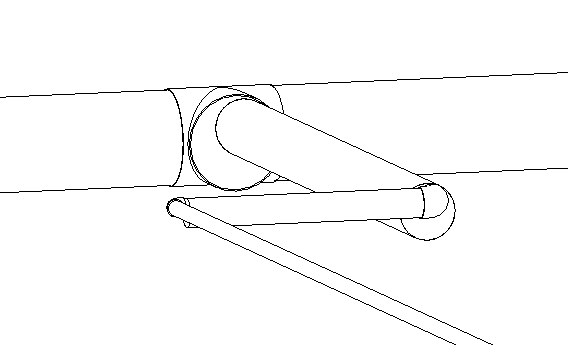
 Control Point to select the end of the ductwork section that will be used as the reference for justification as indicated by an arrow that appears at the end of the branch.
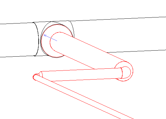
Each click alternately selects the starting segment or ending segment as indicated by an arrow at either end of the branch.
- Specify the alignment reference:
Click... to align to the... 
Top Left 
Top Center 
Top Right 
Middle Left 
Middle Center 
Middle Right 
Bottom Left 
Bottom Center 
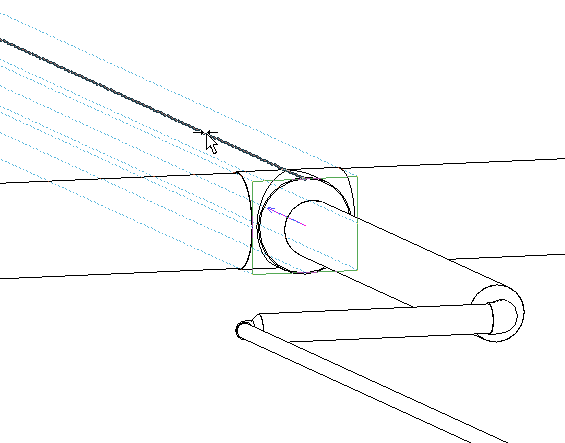
Bottom Right You can also click Alignment Line, and select a reference line in the drawing area. This feature is most useful in a 3D view with Thin Lines selected and Visual Style set to Wireframe. It displays dashed reference lines at the edges and along the center of the faces of the reference pipe as shown. Note: You must specify Wireframe for Visual Style before using the justification editor.
 - Click one of the alignment lines in the drawing to specify the line to be used for justification.
- When you are satisfied with the justification settings for the piping, click
 Finish to align the piping, or click
  Cancel to dismiss the justification editor without applying the changes.
 The piping shown here has been justified to the Top Center of the large segment connected to the tee.