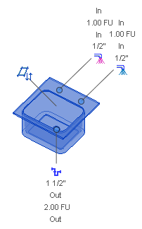
You can view the properties of a system connector before connecting to it by displaying the connector label.
Each system connector has a label and leader that displays the system type and connector data, typically size, flow direction, and flow/fixture units.
In any view, select a system device (equipment or fixture) to display the connector labels. 

A leader line displays from each connector to a system type symbol outside of the bounding box of the fixture, preferably in the direction of the connector.
Click the system type icon to start the draw command and inherit the size and elevation from the connector.