Learn how concrete beams and columns display when obscured in a view.
You control how hidden lines for concrete structural framing elements with the Display in Hidden Views family parameter. To access the parameter:
- Select the concrete beam or column and click Modify | Structural <Element> tab
 Mode panel
 (Edit Family).
- Change the parameter in one of two places:
- Locate Display in Hidden Views under Graphics in the Properties palette.
- Click Create tab Properties panel
 (Family Category and Parameters). Locate Display in Hidden Views under Family Parameters in the Family Category and Parameters dialog.
Note: This parameter is only available to structural beams and columns constructed from concrete.
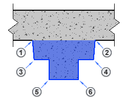
The following pan joist beneath a structural floor demonstrates how the Display in Hidden Views parameter affects views. Each numbered corner in this section view represents a beam edge that can be hidden by geometry.
 The following table shows how the parameter setting affects these edges.
| Parameter setting and description | Plan view as specified |
|---|---|
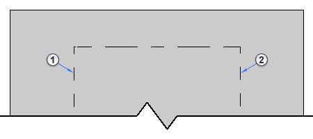
| Edges Hidden by Other Members. Displays the edges of the element that are obscured by other elements.
In this plan view, a structural floor obscures the beam edges 1 and 2 and the beam ends which display as dashed lines. |
|
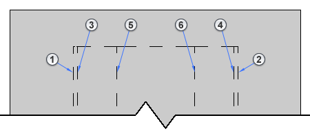
| Edges Hidden by Beam Itself. Displays the edges of the element that are obscured by the geometry of the beam.
In this plan view, the beam geometry obscures the beam edges 3, 4, 5, and 6 which then display as dashed lines. |

|
| All Edges. Displays all edges of the element.
In this plan view, all obscured edges and the beam ends display as dashed lines. |
|
Note: Increase the scale of the view if the dashed lines are too small or not appearing.