3D controls display from points, edges, vertexes, or surfaces on some selected elements that require coordinate direction manipulation.
Use this control to directly manipulate a form by dragging it along the axes or planes defined by the global or local coordinate systems.
|
The global coordinate system is based on the North, East, South, and West coordinates of the project. |

|
A local coordinate system is based on a specified point of reference in the family or model such as surfaces, edges, or reference planes. |
|
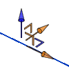
Mixed systems can be created if geometry of the host element is repositioned. For example, if you rotate a cube by 15 degrees, the X and Y arrows display in orange, but the Z arrow remains blue because it still has the same global Z coordinate value. |
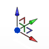
The arrow controls move along an axis, the angle-shaped controls move along the plane.
| Use the... | To drag the object... |
|---|---|
| Blue arrow | along the global Z axis (up and down) |
| Red arrow | along the global Y axis (east and west) |
| Green arrow | along the global X axis (north and south) |
| Red planar control | in the Y plane |
| Green planar control | in the X plane |
| Orange arrow | along a local axis |
| Orange planar control | in a local plane |
Note: In the Conceptual Design Environment, you can switch this orientation between a global and local, coordinate system by pressing the Spacebar.
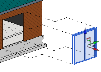
The following graphic displays a door being displaced for documentation using the 3D controls.