Display Results on Members in Tabular Form
Learn how to display internal forces and displacements for particular load cases and combinations.
-
Continue working in your project or open the project Frame_3D_Analysis.rtd.
Note: The Tutorial files are located in C:\ProgramData\Autodesk\Examples\Tutorials. -
In the Standard toolbar, expand the Layouts drop-down menu and select Results as shown below:
The layout is divided in three parts: View, Diagrams dialog and Reactions in the coordinate system table.
-
Click View > Tables.
Alternatively, right-click in the View-Cases window, and then click Tables from the context menu.
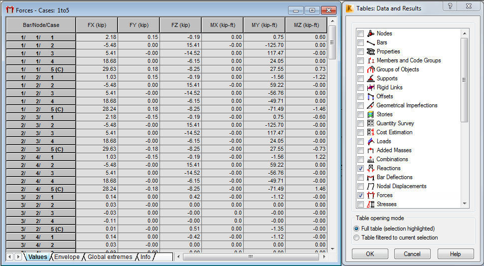
The Tables: Data and Results dialog opens.
-
Select Forces, and then click OK.
Alternatively, click
 (Forces - Table) in the Structure Model toolbar on the right side of the program.
The Forces table opens and displays information about internal forces. Tabs are available at the bottom of the table, allowing you to visualize information on Values, Envelope, and Global Extremes data.
-
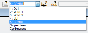
In the Cases Selection box of the Selection toolbar, expand the Cases drop-down menu and select 5: COMB1.
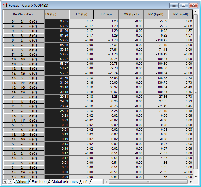
The table updates and presents the results for the COMB1 case.
-
In the Forces table, double-click the FX column header to sort the forces from the maximum to the minimum values.
-
Click View > Tables.
Alternatively, right-click in the View-Cases window, and then click Tables from the context menu.
The Tables: Data and Results dialog opens.
-
Select Nodal Displacements, and then click OK.
Alternatively, click
 (Displacements) in the Structure Model toolbar on the right side of the program.
 -
Right-click in the Displacements table, and then click Table Columns from the context menu.
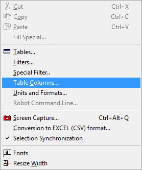
-
In the Nodal value selection dialog:
- Go to the Displacement tab, and select U - total displacements,
- Go to the General tab, and then select Coordinates from the Element data selection group.
-
Click OK.
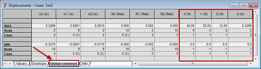
Four new columns are added to the Displacements table (as shown in the image below).
-
In the Displacements table, go to the Global extremes tab located at the bottom of the table.
-
Close the Displacements and Forces tables.