Display Configuration
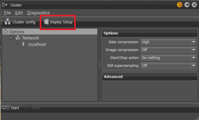
Click the Display Setup option in the Rendering > Cluster dialog to access the display configurations.


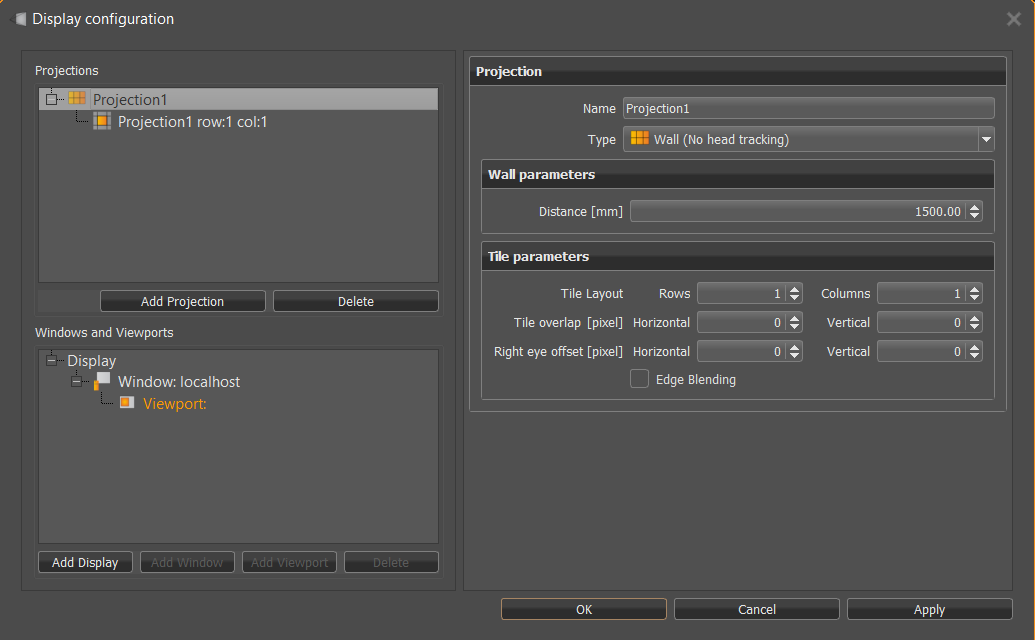
Projections
Lists all projections. Right-click for options to copy, paste, delete, and add projections, as well as convert them to planes.
There are Add Projection and Delete buttons to do the same.
When a projection is selected, the Projection options are loaded into the pane to the right.
Windows and Viewports
Right-click for options to copy, paste, delete, and add display, window, and viewport, as well as delete anything selected in this section.
There are Add Display, Add Window, Add Viewport, and Delete buttons to do the same.
When the following is selected, its options are loaded into the pane to the right.
With Display selected, the Display options are loaded.
With Window selected, the Window options are loaded.
With Viewport selected, the Viewport options are loaded.
Projection Options
Name
This name is used to assign projections to windows.
Type
Contains the following type options:
Wall (No head tracking)
For a tiled display without head tracking support. Select this type for a tiled wall. In a tiled wall projection setup, a projection is composed of multiple projectors or multiple displays. Each projector or display projects a tile of the full image. Tiles are arranged in rows and columns. Rows are counted from bottom to top and columns are counted from left to right. Tiles can overlap each other and the overlapping edges can be blended. If stereo display has an offset between the left and the right eye, then the offset from the left to the right eye must be provided.
| Row 3 Col 1 | Row 3 Col 2 |
| Row 2 Col 1 | Row 2 Col 2 |
| Row 1 Col 1 | Row 1 Col 2 |
There are two similar tiled projections supported. The first one does not support head tracking. For this setup, the exact geometry of the display must not be provided. So, if head tracking is not required, this setup should be used.
Wall Parameters
- Distance - Sets the zero-parallax distance in mm.
Power Wall
For a tiled display with head tracking support. The projection plane must be defined in mm. The center of the tracking system must be calibrated to lie in the center of the projection wall.
Power Wall Parameters
Projection Area [mm] - Sets the width and height of the projection in mm.
Distance - Sets the sistance from the origin of the tracker to the projection plane.
Cave
For a cave-like projection. A cave consists of multiple orthogonal projections. It is defined as a cube. Each side of the cube can be defined as a projection plane. Consider a person standing in the middle of the cave cube, then the projection planes are named relative to this person as front, back, left, right, bottom and top. If the walls of the cave are not aligned to a cube, for example the floor projection is shorter than the left or right wall, then multiple cave projections can be used or some sides of the cave can be defined as projection planes.
Cave Parameters
Cave Size [mm] - The size of the cave cube in mm.
Cave Center [mm] - Distance from the origin of the tracker to the cave center.
Cave Walls - Select the walls to use.
Plane
A projection plane is the most flexible projection type. It is possible to define any rectangular area in 3D space as a projection area. The plane is defined by 3 points in space.
Plane Parameters
- Projection Plane - 3 corner points of the projection plane must be defined in counter clock order.
Tile
Adds the two tile projection type-specific options, Tile and Right Eye Offset [pixel], to Tile Parameters.
Tile Parameters
Tile - For the Tile projection type only. Defines its size, based on the number of rows and columns.
Tile Layout - Sets the number of vertical rows and horizontal columns.
Tile Overlap [pixel] - Sets the number of pixel for horizontal and vertical tile overlap.
Right Eye Offset [pixel] - For Wall and Tile projection types only. Sets an offset distance from the left to the right eye in pixels for when the left and right eye projections are not congruent.
Edge Blending - Blends overlapping regions.
Display Options
If the projection is defined, then each projection must be mapped to a window on one of the cluster nodes. All windows that belong to the same display are grouped together into a display node.
Eye Separation [mm] - Defines the distance between left and right eyes in millimeters.
Camera - You can set different cameras to each display. Mapping is done by camera name so it can be stored in the display cluster configuration file. If the camera cannot be found, the active camera from the primary host is used.
User - You can specify the tracking user for the projection. With this option, you can drive two different caves with independent head tracking for the same scene. The option can be found in the display settings of the cluster module or in the body options of the tracking module for target type Head Projection.
Hardware Sync - If the graphics driver supports buffer swap syncs, then select this option to synchronize the buffer swaps. To synchronize buffer swaps between multiple cluster nodes, a special sync hardware and sync network is required, for example Quadro Sync from NVidia.
Window Options
Render Node - The name of a compute node that should be used as graphics output.
Screen - If multiple displays are connected, then the screen number is used to select one of the displays.
Full Screen - The whole screen area is used.
Geometry - If Full Screen is not selected, the geometry parameters are used to define an area on the screen where the window should be visible.
Viewport Options
A viewport defines an area on a window where the scene should be visible. Each viewport is responsible to view one projection.
Projection - Select the projection that should be visible on this viewport.
Stereo - Stereo parameter:
Disabled
Left
Right
Double Buffered
Horizontal Interlaced
Vertical Interlaced
Left/Right Split
Top/Bottom Split
Red/Cyan
Blue/Yellow
For definitions of these stereo modes, see Stereo Options in the Visualization Menu.
Position - Defines the position of the viewport in the window. Select Custom to define the exact position in pixels. Viewport positions, Lower left and Upper right, can be defined in pixel values >1 or relative to the window [0-1].
Flip - The displayed image can be mirrored horizontally or vertically.
Click OK and Apply to apply the changes made in this dialog.