Analyzing Surfaces
Examine the continuity of different types of virtual lines like isophotes that are displayed on the objects in the scene, detect discontinuities on surfaces, and analyze polygonal as and NURBS data. This topic describes working with the Isophotes and Reflection Lines modes.
Activate Surface Analysis
- Select Rendering > Surface Analysis to open the Surface Analysis dialog box.
- Select Activate Surface Analysis.
Adjust Settings in Isophotes Mode
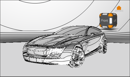
In Isophotes mode, a virtual light source provides defuse illumination to the object geometry. All points sharing the same brightness value are connected with a line.
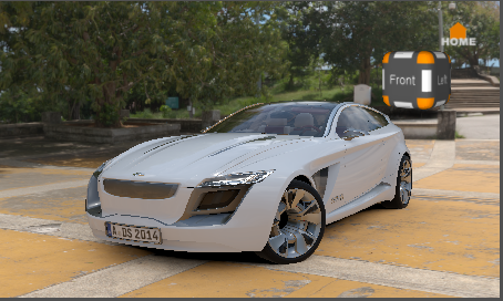
| Surface Analysis Off | Surface Analysis On - Isophotes Mode |
|---|---|
 |
 |
- From the Analysis Mode box of the Surface Analysis dialog box, select Isophotes.
- To orient light direction along an axis, select X, Y, or Z beside Set to Axis (under Define Light Source).
- Select Show Light Direction to show the light direction manipulator.
- To define light direction using the surface normals on your geometry, click Pick Surface Normals, then Shift-drag the manipulator in the scene.
- To align the light along the camera vector, click Use Camera View Vector.
- Under Lines / Stripes, adjust the type, amount, and color of the lines.
Adjust Settings in Reflection Lines Mode
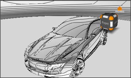
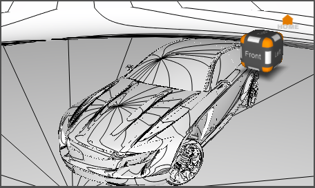
In Reflection Lines mode, lines on a virtual plane are reflected onto the surface of the geometry.
| Surface Analysis On - Isophotes Mode | Surface Analysis On - Reflection Lines Mode (Parallel Linear Lines) |
|---|---|
 |
 |
-
From the Analysis Mode box of the Surface Analysis dialog box, select Reflection Lines.
-
Select Parallel Linear Lines on a Plane.
-
Change the value of Lines Spacing to increase the size of the plane.
-
Alternatively, select Longitudinal Lines on a Sphere under Analysis mode.
This creates a sphere with lines reflected on the geometry.
-
Adjust light direction as you would in Isophotes mode.