About the VRED Toolbar
There are two toolbars in the main VRED Window, the main toolbar and Quick Access Bar.
The VRED Toolbar
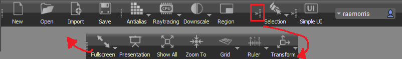
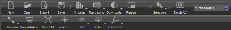
Below the menu bar is the VRED main toolbar. The main toolbar is composed of an assortment of smaller toolbar. These can be dragged into different locations along the top of the VRED application window.
To customize the toolbar further, use the View > Toolbars menu options. When you select View > Toolbars and uncheck options in this menu, they are removed from the main toolbar. To add them back, place checks beside their names in the View > Toolbars menu.
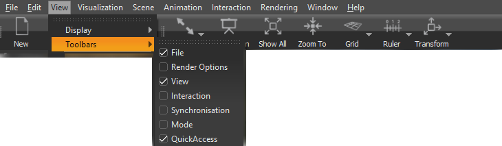
The picture above only displays the relevant part of the View menu.
The UI mode you are in, standard or simple, will also determine the tools you see. Standard UI mode contains all the icons, however, the size of your window determines whether all are visible or not. Whenever you see ![]() , this means there are hidden icons in this group.
, this means there are hidden icons in this group.
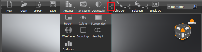
If working with a narrow screen, either open the window to full size or grab and reposition the icon groupings, as shown above. View > Toolbars is only available in standard UI mode.
File
Contains the following options:
New
 Creates a new scene file with four camera views and a default environment. The existing scene is destroyed.
Open
 Opens only VRED files, such as .vpb and .vpe. The existing scene is destroyed. To load other file types into VRED, use File > Import or File > Import Scene Data.
Import
 Loads supported files types into the current scene, merging the geometry with the scene. Adding a VRED scene opens a dialog box for choosing whether to merge variants, touch sensors, sequences, or environments.
Save
 Saves the current scene.
Render Options
Contains the following options:
Antialias
 Toggles stillframe antialiasing in the render view (Viewport). Keep mouse button pressed to select downscale or raytraced antialiasing for OpenGL.Choose from these options:
-
Enable Downscale Antialiasing
-
Enable Raytraced Antialiasing
Raytracing
 Toggles raytracing in the render view (Viewport). Provides the following rendering and raytracing options:
- Rasterizer - Turns on Open GL rendering.
- CPU Raytracing - Turns on raytracing, using your CPU.
- GPU Raytracing - Turns on raytracing, using your GPU.
Downscale
 Toggles downscale raytracing, which controls the quality of the raytracing in the render view (Viewport) by controlling the calculation of the raytracing. Select the downscale quality level. Keep the mouse button pressed for further options: Off, Low, Medium, and High.
Region
 Enables a faster preview of a specific selected region in the Viewport. Only this region is sampled in detail and updated when antialiasing and raytracing are activated. To select a region, hold the R key and drag with the left mouse button.
Isolate
 Isolates the view, so only objects selected in the Scene Graph are visible, hiding everything else.
Sceneplate
 Uses a background image in the Viewport. Keep the mouse button pressed for further options:
- Create Backplate - Selects a backplate image.
- Delete Backplate - Deletes the backplate from the Viewport.
Wireframe
 Applies a wireframe to all selected objects.
Boundings
 Shows or hides a bounding box for the selected object. The bounding box is an orange cube that frames the selection.
Headlight
 Enables or disables the headlight (default light) in the scene.
Statistics
 Toggles the display of a summary of information about the scene. When enabled, it opens a window displaying information, such as Frames per Second (FPS), Triangles drawn displayed, and more.
View
Contains the following options:
Fullscreen
 Enables fullscreen mode. Keep the mouse button pressed for an option to enable multi-display fullscreen. Press Esc to deactivate it.
Presentation
 Toggles Presentation Mode. In Presentation Mode, only the hotkeys from the Variants module are available.
Show All
 Zooms out until all objects inside the Scene Graph are visible inside the render view (Viewport).
Zoom To
 Zooms into the objects selected in the scene.
Grid
 Shows or hides a grid for measurements that can help to identify geometry proportions. Keep the mouse button pressed for further options:
xy/xz/yz
Changes the orientation of the grid.
Show Labels
Shows or hides the measurement values within the grid.
Settings
Opens a dialog box to adjust grid size and subdivisions.
Ruler
 Shows or hides a ruler on the ground plane in the render view to help with estimating distances. Shift-click to set the ruler's position.
Show Manipulator
Enables a transformation and rotation manipulator for positioning the grid within the scene. Shift-click to position the ruler on a geometry point.
Show Grid
Shows a grid with the ruler.
Fix Axes
If disabled (default), the ruler scale markings and the grid adapt to the distance of the camera and the ruler origin. If Fix Axes is activated, the scale and grid remain static during camera movement.
Transform
 Shows a transform manipulator in the render view to reposition the selected geometry. Keep the mouse button pressed for further options:
Local Mode
If enabled, the translation manipulator is oriented by the local coordinate system of the object.
Use Fixed Steps
Enables only full numerical transformation/rotation/scales. During manipulation, the relative translation/rotation/scale values snap to a multiple of the step size defined in the Preferences Transform.
Size
Shows a control for changing the size of the transformation tool.
Translation, Rotation, or Scale Manipulator
Shows these specific manipulators.
Universal Manipulator
Do any type of manipulation.
Pivot Transform Manipulator
Repositions the pivot point of the selected object.
Interaction
Contains the following options:
Selection
 Sets what can be selected. Choose from Component, Object, Group, By Material, or Adjacency. If Adjacency is selected, use the Adjacency Settings to select the method used, Picked Normal or Neighbor Normal, and set the angle.
Texturing
 Toggles display of the material texture manipulator on selected objects. Use the manipulator to change the texture mapping on the material. Manipulators are available for the tire material, and all materials using Planar, Triplanar, and UV mapping types. For more UV mapping or projection options use the UV Editor.
When Texturing Mode is activated, Shift-click in the render view to open the appropriate texture manipulator to select the texture.
Click-hold ![]() to access the Texture Manipulator Settings dialog.
to access the Texture Manipulator Settings dialog.
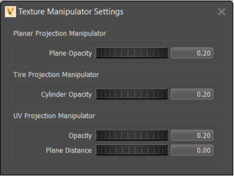
Use it to set the visibility of following:
Planar Projection Manipulator
Click here to view the Quick Tip - Planar Projection video.
Changes the visibility of the planar projection plane when using a decal image. Adjust Opacity from 0 (not visible) to 1 (fully visible).
Tire Projection Manipulator
Changes the visibility of the cylindrical projection plane used for tires.
UV Projection Manipulator
Changes the visibility of the planar projection plane and general opacity of the UV projection manipulator
Synchronization
Contains the following two options:
Connect
 Toggles the connection to another VRED.
Cluster
![]() Toggles the connection to the cluster.
Toggles the connection to the cluster.
Mode
Contains the Simple UI option:
Simple UI
 Toggles between the standard full UI and a simplified subset of the UI. The Simple UI limits the number of available features to simplify the visualization process.