Customizing Controls and Display
Customizing controls and your display is possible using an assortment of tools.
How to Adjust the VRED Display
In the Menu Bar, select View > Display, then a display setting that is appropriate for the device you are using:
If the View option is not displayed, at the far right of the Icon Bar, turn off Simple UI.
Powerwall Settings
Opens the Powerwall Settings Editor containing the following attributes:
- Width and Height - Sets the dimensions of the projection window.
- Distance - Sets the distance between the projection window and viewer.
- Enable Powerwall Mode - Activates Powerwall rendering.
Standard Display
Encodes the rendered image to be displayed on a standard display.
HDR10 Display
Automatically turns on HDR rendering in Windows, if it is not already enabled, and disables VRED's internal color management, so Windows can take over full color management control. For information on HDR Light Studio settings when working with area lights, see How to Connect Area Light to HDRLS.
SIM2 HDR
Encodes the rendered image to be displayed on an HDR display.
Sony 10bit
Encodes the rendered output image with 10-bit color depth.
Oculus Rift
Generates output images optimized for Oculus Rift devices.
OpenVR HMD
Enables head mounted VR devices to connect to VRED via the OpenVR. VRED uses the OpenVR 1.12.5 SDK.
How to Split the View
Splits the Viewport into perspective, front, side, and top views.
In the Menu Bar, select Window > Show Split View.
If the View option is not displayed, at the far right of the Icon Bar, turn off Simple UI.
How to Return to a Single Display
To return to a single display view, in the Menu Bar, click Window > Show Single View to display single view. The last active window, indicated by a white border, will become the single view.
For a shortcut to toggle between split view and single view, use Ctrl+Space Bar.
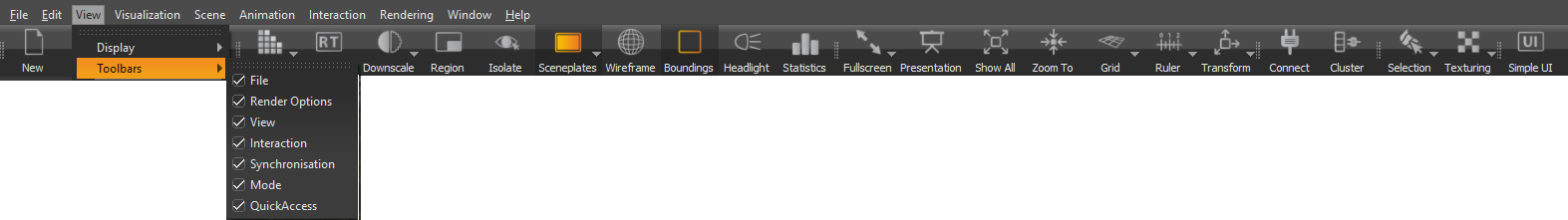
How to Show or Hide Toolbars
Select which toolbars are visible in the main VRED window. Show or hide tools.
In the Menu Bar, select View > Toolbars, then select one or more options.
-
When checked, the tools in that toolbar appear in the main VRED toolbar.
-
When unchecked, the tools in that toolbar will be removed from the main VRED toolbar.
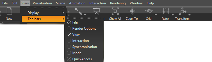
If the View option is not displayed, at the far right of the Icon Bar, turn off Simple UI.
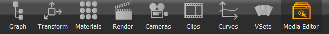
Customizing the Quick Access Bar
You can add to, rearrange, and delete tools from the Quick Access Bar, as well as save various configurations. Since the default layout cannot be changed, custom layouts must be saved. If you’ve accidentally changed a layout, follow the steps in the sections below to add, rearrange, delete a tool or tools, then save the change or select Window > Layout > Default to return to the default layout.
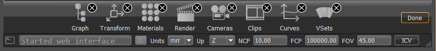
How to Delete a Tool from the Quick Access Bar
-
Double-click and hold a tool in the Quick Access bar, to access the
 .
. -
To delete a tool, click the
belonging to that tool. -
When finished, tap Done.
How to Add Tools to the Quick Access Bar
If you are looking for a toolbar with Assets, Scene, Animation, Variants, and Render in it, click  (the Simple UI mode) to change it. See Switching Interfaces.
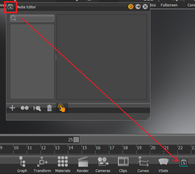
Click-hold the icon at the top left corner of any module and drag it onto the Quick Access Bar. This adds it to the far right of the bar.
How to Reorder Tools in the Quick Access Bar
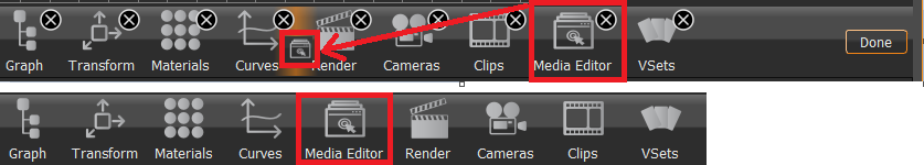
- Click-hold until the toolbar changes to its edit mode.
- Click-drag a tool icon to any place in the toolbar.
- Click the Done button to exit the edit mode.
How to Save a Custom Layout
Use Window > Layout > Save or Save As. If you've made changes to an existing layout, use Save to save the changes. However, for creating a new layout, use Save As.
- Select Window > Layout > Save As.
- In the Store Current Layout dialog, name the layout and click OK.
How to Set the Quick Access Bar Configuration Used at Startup
To set the Quick Access Bar used upon startup, use Window > Layout > Edit.
- Select Window > Layout > Edit.
- In the Edit Layouts dialog, open the Start Layout menu and select the layout.
- Place a check next to the layout to use at startup.
- Click Close.
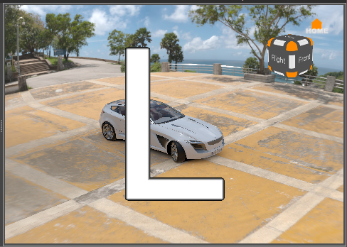
How to Identify Stereo Output Channels
In the Menu Bar, select View > Stereo Identification. A letter appears in the Viewport.
If the View option is not displayed, at the far right of the Icon Bar, turn off Simple UI.
How to Show Scene Elements and Controls
In the Menu Bar, from the View menu, select the appropriate option.
-
Show A Sides, Show B Sides, Show A and B Sides - Faces in 3D data can be defined as an A or B side. Use these options to select which faces to show. More options are available in the Scene Graph View menu.
-
Show Cameras - Shows or hides all cameras.
-
Show Lights - Shows or hides all lights.
-
Show Camera Pivot - The point that the camera rotates around is displayed within the Viewport during camera rotation.
-
Show Annotations - Shows annotations (notes) that were created under Interaction > Annotation.
Note:If the Annotation window is open, another way to turn an annotation on or off is by clicking
 .
. -
Show Clipping - Shows the clipping plane created under Interaction > Clipping.
-
Show Grid - Shows the scene grid in the Viewport. This provides a grid (axis) on the floor that helps with estimating distances.
-
Show Measurement - Shows measurements created under Interaction > Measurement.
-
Show Ruler - Shows the ruler in the scene.
-
Show Manipulator - Shows the transform manipulator.
-
Show Routes - Opens a new window and displays all VRML animation routes in the scene.
-
Show Shortcuts - Opens a new window and displays all available VRED shortcuts.
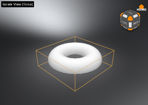
How to Show or Hide Selected Content
To show or hide everything that is currently selected, in the Menu Bar, select Visualization > Isolate View Selected. This adds an Isolate View (name of the selected node) label to the Viewport. Visibility of environments and backplates is not affected. In previous versions of VRED, this feature was available by dragging a node from the Scene Graph into the Viewport.
How to Show a Simulation of a Scene
In the Menu Bar, select Visualization > Simulate. This starts the simulation loop to control animations, interactive scripts, viewpoint interpolations, and other functions.
How to Get the Serial Number For a VR Device
Use the following Python scripts for calling a tracker by a VR device's serial number, creating a node, and attaching the node to a tracker.
- Use
tracker1 = vrDeviceInputMapperService.getVRDeviceBySerialNumber(serial number)to identify a tracker by acquiring a serial number for a VR device. - Use
box = vrNodeService.getNodeFromId(createBox(100,100,100,1,1,1,1.0,0.0,0.0,0.0).getID())to create a node. - Use tracker1.getNode().addChild(box) to attached the node to the tracker. This will be useful when printing out a list of devices by serial number.
How to Print a List of Serial Numbers and Devices
Once you have gone through the steps in How to Get the Serial Number For a VR Device, use the following Python scripts to print a list of VR devices and serial numbers.
-
Use
devices = vrDeviceService.getConnectedVRDevices()to generate a list of connected VR devices. -
Use the following to get a list of device names and device serial numbers:
print(device.getName())
print(device.getSerialNumber())