Axisymmetric Triangular Element Connection
Description: Defines an isoparametric axisymmetric triangular cross-section solid element with midside grid points.
Format:

Example:

| Field | Definition | Type | Default |
|---|---|---|---|
| EID | Element identification number. | Integer > 0 | Required |
| MID | Material identification number. | Integer > 0 | Required |
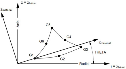
| Gi | Grid point identification numbers of connection points. | Integer > 0, all unique | Required |
| THETA | Material property orientation angle in degrees. | Real | 0.0 |
Remarks:
- Element identification numbers must be unique with respect to all other element identification numbers.
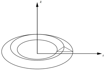
- The grid points must lie in the x-z plane of the basic coordinate system, with x = r ≥ 0. The grid points must be listed consecutively beginning at a vertex and proceeding around the perimeter in either direction. If the ID of any edge connection points is left blank or set to zero, the element equations are modified to give the correct results for the reduced number of connections. Corner grid points cannot be deleted.
- For structural problems, the MID must reference a MAT1 or MAT3 material entry.
- The continuation is optional.
- Material properties (if defined on a MAT3 entry) and stresses are given in the
 coordinate system shown in Figure 2.
- A concentrated load (e.g.,
FORCE entry) at Gi is divided by the
 times the radius to Gi and then applied as a force per unit circumferential length. For example, in order to apply a load of 100 N/m on the circumference at G1 (which is located at a radius of 0.5 m), the magnitude of the load specified on the static load entry must result in:


Figure 1. CTRAX6 Element Idealization

Figure 2. CTRAX6 Element Geometry and Coordinate Systems