Weld or Fastener Element Connection
Description: Defines a weld or fastener connecting two surface patches or points.
Format:

Example:

Alternate Formats and Examples:

| Field | Definition | Type | Default | ||||||
|---|---|---|---|---|---|---|---|---|---|
| EID | Element identification number. | Integer > 0 | Required | ||||||
| PID | Property identification number of a PWELD entry. | Integer > 0 | Required | ||||||
| GS | Identification number of a grid point which defines the location of the connector. Required for GRIDID and ELEMID. See Remark 2. | Integer > 0 | |||||||
| FTYPE | Connection format type, one of the following character variables: GRIDID, ELEMID, or ALIGN.
|
Character | Required | ||||||
| GA, GB | For FTYPE = GRIDID or ELEMID the grid identification numbers of piercing points on surface A and surface B, respectively. For FTYPE = ALIGN the vertex grid identification numbers of the first and second shell elements respectively. | Integer > 0 | See Remark 7 | ||||||
| GAi | For FTYPE = GRIDID the grid identification numbers of the first surface patch. GA1 to GA3 are required. See Remark 6. | Integer > 0 | See Remark 8 | ||||||
| GBi | For FTYPE = GRIDID the grid identification numbers of the second surface patch. See Remark 6. | Integer > 0 | See Remark 8 | ||||||
| SHIDA | For FTYPE = ELEMID the element identification number of the first shell element. | Integer > 0 | See Remark 5 | ||||||
| SHIDB | For FTYPE = ELEMID the element identification number of the second shell element. | Integer > 0 | See Remark 5 |
Remarks:
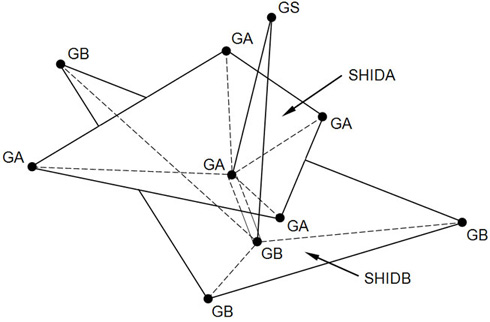
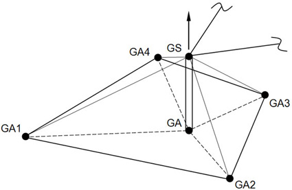
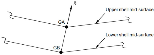
- CWELD defines a flexible connection between two surface patches, between a point and a surface patch, or between two shell vertex grid points.

Figure 1. Patch-to-Patch Connection Defined with FTYPE Equal to GRIDID or ELEMID

Figure 2. Patch-to-Point Connection Defined with FTYPE Equal to GRIDID or ELEMID

Figure 3. Point-to-Point Connection Defined with FTYPE Equal to ALIGN
- Element identification numbers should be unique with respect to all other element identification numbers.
- The location of the connector element is defined by a projection of grid point GS normal to surface patches A and B. A normal projection must exist in order to define a valid element. GS need not lie on either surface patch, and is ignored if FTYPE = ALIGN.
- FTYPE = GRIDID defines either a point to patch or a patch to patch connection. For the point to patch connection, the user must define GS and GAi. Then it is assumed that GS is a shell vertex grid and GAi are grids describing a surface patch. For the patch to patch connection, the user must define GS, GAi and GBi. Then GAi describes the first surface patch and GBi the second surface patch.
- FTYPE = ELEMID defines a point to patch connection, GS to SHIDA or a patch to patch connection, SHIDA to SHIDB. SHIDA and SHIDB must be valid shell element identification numbers.
- FTYPE = ALIGN defines a point to point connection. GA and GB are required, and they must be vertex nodes of shell elements. GA and GB are not required for the other formats.
- The input of the piercing points GA and GB is optional for FTYPE = GRIDID and ELEMID. If GA and GB are not specified, they are generated from the normal projection of GS on surface patch A and B. If GA and GB are specified, their locations may be corrected so that they lie on surface patch A and B, respectively. The length of the connector is the distance from GA to GB.
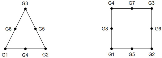
- GAi are required for FTYPE = GRIDID. At least 3 and at most 8 grid point identification numbers may be specified for GAi and GBi, respectively. Triangular and quadrilateral element definition sequences apply for the order of GAi and GBi.

Figure 4. Triangular and Quadrilateral Surface Patches Defined with Format GRIDID
- Forces and moments are output in the element coordinate system. The element x-axis is in the direction of GA to GB. The element y-axis is perpendicular to the element x-axis and is lined up with the closest axis of the basic coordinate system. The element z-axis is the cross product of the element x-axis and y-axis. The output of the forces and moments including the sign convention is the same as in the CBAR element.