创建零件
定义零件几何图形通常是开发有限元模型的第一步。
此处,定义了板几何图形,以便生成三维零件。
使用“Helius PFA for ANSYS 启动程序”工具(如下所示)打开 ANSYS Mechanical APDL。此工具将通过必要的环境变量启动 ANSYS,从而使 Helius PFA 与 ANSYS 一起运行。
此工具随 Helius PFA 一同安装,可在桌面上找到。它还可能位于以下路径:
%install_dir%\bin\ansys-helius-launcher.exe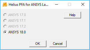
在 ANSYS Mechanical APDL 产品启动程序中单击“Run”按钮。将显示 ANSYS GUI。
为生成均匀的映射网格,板将分为 8 个体积。
依次单击“Main Menu”>“Preprocessor”>“Modeling”>“Create”>“Volumes”>“Block”>“By 2 Corners & Z”。
在显示的对话框中,输入以下值,然后单击“Apply”按钮:
- WP X = 0
- WP Y = 0
- Width = 0.75
- Height = 2.25
- Depth = 0.144
每次为 WP X、WP Y、宽度、高度和深度输入下列值时,重复步骤 4:
- 0.75, 0, 0.75, 2.25, 0.144
- 0, 2.25, 0.75, 0.75, 0.144
- 0.75, 2.25, 0.75, 0.75, 0.144
- 0, 3, 0.75, 0.75, 0.144
- 0.75, 3, 0.75, 0.75, 0.144
- 0, 3.75, 0.75, 2.25, 0.144
- 0.75, 3.75, 0.75, 2.25, 0.144
依次单击“Main Menu”>“Preprocessor”>“Modeling”>“Create”>“Volumes”>“Cylinder”>“Solid Cylinder”。
在显示的对话框中,输入以下值,然后单击“OK”:
- WP X = 0.75
- WP Y = 3.0
- Radius = 0.125
- Depth = 0.144
依次单击“Main Menu”>“Preprocessor”>“Modeling”>“Operate”>“Booleans”>“Subtract”>“Volumes”。
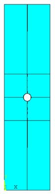
选择在步骤 4 和 5 中创建的 8 个块,然后单击“OK”。当系统提示您选择要减去的体积时,拾取圆柱体,然后单击“OK”。板应如下所示。
要完成几何图形,必须合并这 8 个体积。依次单击“Main Menu”>“Preprocessor”>“Modeling”>“Operate”>“Booleans”>“Glue”>“Volumes”。选择 8 个体积,然后单击“OK”。