The Reinforcement tab allows you to define reinforcement parameters.
Access
- Click Design
 Required Reinforcement of Slab/Walls - Options Code parameters to open the Plate and Shell Reinforcement Type dialog, and then click
  .
. - Click
 (Plate and Shell Reinforcement Type) to open the Plate and Shell Reinforcement Type dialog, and then click .
Dialog elements
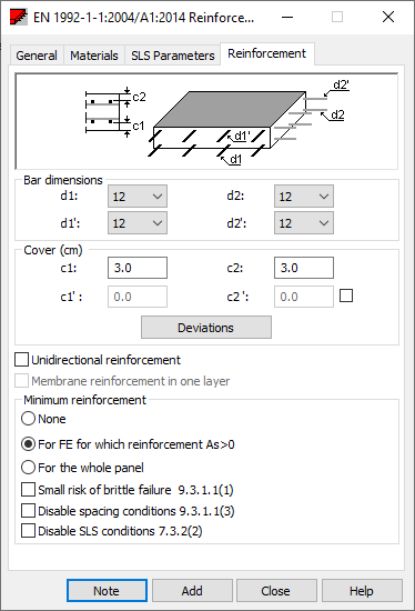
- Bar types
-
Define the following reinforcing bar diameters:
- Diameter d1 - the diameter of reinforcing bars of the bottom main reinforcement
- Diameter d1' - the diameter of reinforcing bars of the top main reinforcement
- Diameter d2 - the diameter of reinforcing bars of the bottom reinforcement perpendicular to the main reinforcement.
- Diameter d2' - The diameter of reinforcing bars of the top reinforcement perpendicular to the main reinforcement
Note: Reinforcing bars located on the main reinforcement direction are exterior bars. In bottom reinforcement they appear on the lower layer and in top reinforcement, in the top layer. - Cover
-
Define the following reinforcing covers:
- Cover c1 - bottom reinforcement cover
- Cover c2 - top reinforcement cover
- Values c1' and c2' - distances of the bottom and top reinforcements, respectively, from the slab reinforcement in the other direction (by default, they are not available until they are selected).
Note: Cover is taken from the plate edge to the exterior surface of the main reinforcing bars. - Additional parameters
-
Define the following additional parameters:
- Unidirectional reinforcement. When selected, only the main direction reinforcement will be calculated (forces acting in the perpendicular direction are ignored). This offers two-fold acceleration of calculations. Note that a simplification is adopted here, which is based on negligible influence (or lack of influence at all) of forces acting in the perpendicular direction. On the main reinforcement verification of user defined settings is not made. Improper use of the option may result in wrong results. Codes for RC element design often require that distributed reinforcement be provided for the direction perpendicular to the main reinforcement direction. The area of distributed reinforcement is not calculated.
- Membrane reinforcement in one layer (in axis). Compression/tension type must be selected on the General tab for this option to be available. When selected, reinforcement is positioned in axis of an RC element (reinforcement will be subjected to compression / tension due to membrane forces).
The following table shows the required parameters for Unidirectional reinforcement and Membrane reinforcement in one layer (in axis) when they are selected or deselected.
Reinforcement Option
Required Parameters
Unidirectional
In one layer (in axis)
d1
d2
d1'
d2'
c1
c2
Yes
No
Yes
Yes
Yes
Yes
Yes
Yes
No
Yes
Yes
Yes
No
No
No
No
Yes
No
Yes
No
Yes
No
Yes
Yes
Yes
Yes
Yes
No
No
No
No
No
- Minimum reinforcement
-
Specify the following criteria of generating the minimum reinforcement in RC panels:
- None. The minimum reinforcement will not be generated in a panel.
- For FE for which reinforcement As > 0. The minimum reinforcement will be generated only in those panels for which the calculated reinforcement is less than the minimum reinforcement and greater than zero. If the calculated reinforcement area for a (triangular) finite element equals zero, then the minimum reinforcement will not be generated.
- For the whole panel. The minimum reinforcement will be generated for a whole panel.
You can also define additional parameters for the control of minimum reinforcement which may be available for ACI 318 and EN 1992-1-1:2004 AC:2008 with all National Annexes codes.
- Small risk of brittle failure. The minimum reinforcement will be generated as 1,2 times the area required in ULS verification.
- Disable spacing conditions. The minimum reinforcement will be generated without limiting the spacing of bars.
- Disable SLS conditions. The minimum reinforcement required to control cracking will be generated without taking the SLS conditions into account.
Minimum reinforcement considers all code combinations and all load cases. Reinforcement may be calculated for one side of a section, both sides, and for a whole section (separately for each instance) depending on code requirements.
Verification starts with checking the total minimum reinforcement. If there is such a condition, it checks if the sum of the bottom and top reinforcements is less than the total amount. If it is greater, then conditions are satisfied and calculations are stopped.
If the sum is less, then:
- The maximum value of the bottom reinforcement and the minimum bottom reinforcement areas are assumed.
- The maximum value of the top reinforcement and the minimum top reinforcement areas are assumed.
The minimum total reinforcement is divided by the sum of the maximum values. The coefficient obtained is denoted by m. Next, the coefficient is multiplied by the maximum values of the bottom and top reinforcements. Their sum will equal the area of the minimum total reinforcement.
Data:
AsTotmin
AsUppmin
AsLowmin
AsUpp
AsLow
AsUpp'=max(AsUppmin; AsUpp)
AsLow'=max(AsLowmin; AsLow)
m= AsTotmin/(AsUpp'+AsLow')
m*AsUpp'+m*AsLow'=AsTotmin.