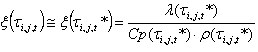
The equation of the heat flow inside the contour shown below may be presented as follows.
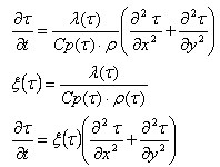
where:
C p - Specific heat (J/kg*K)
λ - Thermal conductivity (W/m*K)
ρ - Unit weight (kg/m 3).
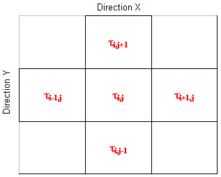
In the differential notation the heat flow equations can be written as:
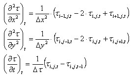 .
.
These equations yield:
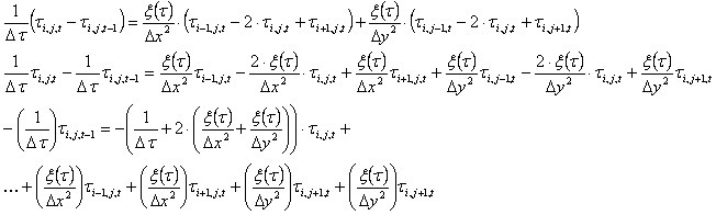 .
.
Thus, for K nodes, the system of equations M[KxK] x τ[K] = B[K] will be solved.
Adopted approximations
When it is required to know the current temperature to determine coefficients not described by equations, the approximation from previous time steps is applied (forward difference).
For the constant time step Δτ, the following is obtained:
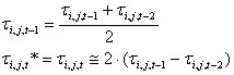
which allows determining:
for the step i = 1 t i,j,1 * = t i,j,o.
Boundary conditions
To the general formulation of the problem, third type boundary conditions are added which are responsible for:
- Convection
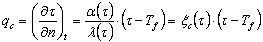
where:
n - Normal to the edge
Tf - Temperature in the outer environment of the contour identified with the fire temperature.
Assuming that the convection coefficient a is independent of temperature and adopting the approximations discussed earlier, the following is obtained:
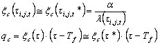 .
. - Radiation
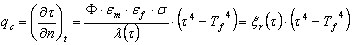
where:
n - Normal to the edge
T f - Temperature in the outer environment of the contour identified with the fire temperature
Φ - Configuration coefficient
ε m - Element emission factor
ε f - Fire emission factor
σ - Boltzman constant 5.65*10 8 (W/m 2 *K 4 ).
Adopting the approximations discussed earlier, the following is obtained:
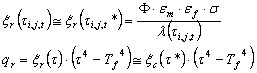 .
.
Assumptions adopted for the DTU P 92-701 code
- Fire development in time
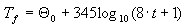
The fire described in a discreet (tabular) form based on the following formula:
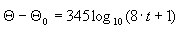 (section 4 DTU P 92-701, figure 11)
 The fire described in a discreet (tabular) form based on the following formula:
where t expressed in [min]
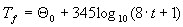
which allows describing the fire temperature as:
Discreet values are selected in such a way so that no temperature increment greater than 30% takes place in any time increment. Linear interpolation is performed between these values.
A description of the fire development in time is included in the file Fire_DTU.t
- Thermal conductivity of concrete
The dependence of thermal conductivity is presented in a tabular form (section 3,15 DTU P 92-701).
A description of the thermal conductivity behavior depending on temperature is given in the file Lambda_DTU.la.
- Unit weight of concrete
It is independent of temperature and equals 2400 [kg/m3].
A description of the unit weight behavior depending on temperature is given in the file Ro_DTU.cp.
- Specific heat of concrete
It is independent of temperature and equals 921.096 [J/kg *K], i.e. 0.22 [kcal/kg * OC] (section 3,16 DTU P 92-701).
A description of the specific heat behavior depending on temperature is given in the file Cp_DTU.cp.
- Reduction coefficient for concrete capacity
The reduction coefficient for concrete capacity is presented in tabular form (section 3.13 DTU P 92-701).
A description of behavior of the concrete capacity reduction depending on temperature is given in the file fic_DTU.cfc.
- Reduction coefficient for steel capacity
The reduction coefficient for steel capacity is presented in a tabular form (section 3.13 DTU P 92-701).
A description of behavior of the steel capacity reduction depending on temperature is given in the file fiy_DTU_1_2.cfy.
In the case steel types 3 and 4 are used, set the file fiy_DTU_3_4.cfy, instead of a default.
- Calculation parameters
Coefficients for radiation:
Φ*εm*εf = 0.85 analogously to the coefficient (section 4 DTU P 92-701)
The above coefficients should be understood as:
Φ - Configuration coefficient
εm - Element emission factor
εf - Fire emission factor
Convection coefficient:
α = 6.9 [W/m2*K] = 6.0 [kcal/m2*h*oC] (section 4 DTU P 92-701)
Assumptions adopted for the EN 1992-1-2 code
- The fire development in time according to EN 1991-1-2
The fire described in a discreet tabular form based on the following formula:

where:
t expressed in [min]
assuming the start temperature 20[ 0C],
which allows describing the fire temperature as:
 .
. Discreet values are selected so that no temperature increment greater than 30% takes place in any time increment. Linear interpolation is performed between these values.
A description of the fire development in time is included in the file Fire_EC2_N.t.
In the case other fire types are used, instead of a default file, set the following:
external fire (section 3.2.2 EN 1991-1-2): Fire_EC2_E.t
hydrocarbon fire (section 3.2.3 EN 1991-1-2): Fire_EC2_H.t
- Thermal conductivity of concrete
The dependence of thermal conductivity is presented in a tabular form (section 3.4 EN 1992-1-2) - on the basis of the lower value of thermal conductivity. Linear interpolation is performed between these values.
A description of the thermal conductivity behavior depending on temperature is included in the file Lambda_EC2_L.la.
In the case the upper value is used, instead of a default file, the user should set the following:
Lambda_EC2_U.la
- Unit weight of concrete
The dependence of the unit weight is presented in a tabular form (section 3.3.2(3) EN 1992-1-2). Linear interpolation is performed between these values.
A description of the unit weight behavior depending on temperature is included in the file Ro_EC2.cp.
- Specific heat of concrete
The dependence of specific heat is presented in a tabular form (section 3.3.2(1) and 3.3.2(2) EN 1992-1-2) on the basis of values for the 1.5% humidity. Linear interpolation is performed between these values.
A description of the specific heat behavior depending on temperature is included in the file Cp_EC2_m015.cp.
In the case other values of concrete humidity are used, instead of a default file, set the following:
0% humidity: Cp_EC2_m000.cp
3% humidity: Cp_EC2_m030.cp
- Reduction coefficient for concrete capacity
The dependence of the reduction coefficient for concrete capacity is presented in a tabular form (section 4.2.4.2 EN 1992-1-2) on the basis of values for concrete with silicate aggregate. Linear interpolation is performed between these values.
A description of behavior of the concrete capacity reduction depending on temperature is included in the file fic_EC2_Si.cfc.
In the case concrete with limestone aggregate is used, instead of a default file, set the following: fic_EC2_Ca.cfc.
- Reduction coefficient for steel capacity
The dependence of the reduction coefficient for steel capacity is presented in a tabular form (section 3.2.3 EN 1992-1-2) based on values for hot-rolled N-grade steel. Linear interpolation is performed between these values.
A description of behavior of the steel capacity reduction depending on temperature is included in the file fiy_EC2_Nhr.cfy.
In the case other types are used, instead of a default file, set the following:
cold-rolled N-grade steel: fiy_EC2_Ncw.cfy.
X-grade steel: fiy_EC2_X.cfy.
- Calculation parameters
coefficients for radiation:
Φ = 1.0 - configuration coefficient (section 3.1(6) EN 1991-1-2)
ε m = 0.8 - element emission factor (section 3.1(6) EN 1991-1-2)
ε f = 1.0 - fire emission factor (section 3.1(6) EN 1991-1-2)
convection coefficient:
α ce = 25 [W/m2*K] on the side exposed to fire (section 3.2.1 EN 1991-1-2)
α cu = 9,0 [kcal/m2*h*oC] on the side not exposed to fire (section 3.1(5) EN 1991-1-2)
Capacity calculation for the BAEL code - axially-compressed columns
Data necessary for calculations:
f cj - Concrete strength automatically transferred from the RobotRC column module.
Φ b - Coefficient for concrete depending on temperature Φ b (τ), in this case, τ is an average temperature inside the section
f e - Steel strength automatically transferred from the Robot RC column module.
φ si - Coefficient for steel depending on temperature φ s(τ), in this case, τ is a temperature in the i-th bar
l - Column height
N - Maximum load applied to the column
α - Coefficient automatically transferred from the RC column module
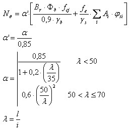
B r = A c - 0.01*u c
Br - Reduced sectional area
A c - Sectional area
u c - Section perimeter
γ b - Coefficient for concrete 1.3
γ s - Coefficient for steel 1.0
A i - Area of the i-th reinforcing bar
Capacity of the column:
N/NQ > 1.0