This option is used for planar finite elements. The Reinforcement tab presents maps or isolines of theoretical (required) reinforcement of slabs/shells obtained during calculations.
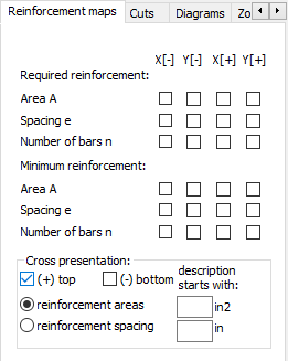
The following values can be chosen for presentation.
- The required (theoretical) reinforcement of slabs/shells: calculated reinforcement areas, reinforcement spacings and numbers of reinforcing bars
- Minimum reinforcement of slabs/shells: reinforcement areas and spacings as well as a number of reinforcing bars.
Individual columns denote:
- X [-]: bottom reinforcement in the X direction (main reinforcement)
- X [+]: top reinforcement in the X direction (main reinforcement)
- Y [-]: bottom reinforcement in the Y direction (perpendicular to the main reinforcement)
- Y [+]: top reinforcement in the Y direction (perpendicular to the main reinforcement).
The location of bottom and top reinforcements in a panel is adopted according to the sense of the z axis of the panel local system. This convention also holds for RC walls.
So, if the sense of the z axis vector of the panel local coordinate system is
![]() , then:
, then:
- Top reinforcement:
 .
.
- Bottom reinforcement:
 .
.
Theoretical (required) reinforcement areas and spacings obtained during the design of a slab/shell structure can be presented in the form of reinforcement crosses. Drawing crosses for top and bottom reinforcement has been split. Cross segments denoting values of top reinforcement are drawn on the positive axis (↑→). Those denoting values of bottom reinforcement are drawn on the negative axis (←↓). It is possible to select drawing the crosses for top and bottom reinforcement simultaneously.
See also:
Method of calculating slab and shell reinforcement area
Selecting RC code that allows calculations according to SLS, presents an additional SLS tab in the Reinforcement dialog.
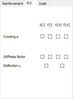
The tab allows selection for presentation (parameters depend on the selected code).
- Cracking width in both directions.
- Stiffness factor (denoted as D / B). The quotient of slab stiffness assumes that the slab material is elastic (as in FEM calculations) and the equivalent stiffness (which accounts for cracking and calculated reinforcement). See also Slab and Shell Deflections - Calculations).
- Deflection u. Real displacements of the calculation point of a slab uR which account for cracking and calculated reinforcement. See also Slab and Shell Deflections - Calculations).