Generate a diagram showing the relationship between a certain result quantity, such as force or displacement at a given point, and a position of the unit force on the load surface.
- Click
Loads
 Special Loads
 Load Pattern.
The
Load Pattern dialog opens.
Load Pattern.
The
Load Pattern dialog opens.
- Click in the Panel box to make it active.
- In the drawing area, select the panel for which you want to generate an influence surface. The Panel box updates with the number of the panel.
- Click Add to define the influence surface. The Definition of influence surface dialog opens.
- Selected a result quantity from a tab, and then click Apply. The selected result quantity is added to the Load Pattern dialog.
- Repeat step 5 for each result quantity that you want to add, and then click
Close.
The selected result quantities are displayed as a list in the
Load Pattern dialog.
Note: If you want to delete a result quantity from the list, select it, and then click Delete.
- Click Generate. The Load Pattern dialog closes, and the Load Pattern - Loads dialog opens. This dialog allows you to display influence surfaces graphically, and also to define new cases and loads.
- To display a color diagram of the influence surface:
- Select one of the defined influence surfaces from the Diagrams of load patterns list.
- Select if you want to visualize the areas where the values of the influence surface are Positive or Negative.
- Optionally, select Open a new window for selection to view the resulting diagram in a new view.
- Click Apply.
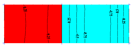
Note: To improve readability, black isolines with descriptions are also drawn on the diagram. Result values are always scaled in order to be contained in the interval: [-1.0, 1.0]. Range limits are determined and equal: -1.0, -0.75, -0.5, -0.25, 0.0, 0.25, 0.5, 0.75, and 1.0. - To define a new load case and planar load on a contour:
- Enter a new case name in the Load case name box, or select one of the defined influence surfaces from the Diagrams of load patterns list.
- Click Add case to generate a new case with the specified name. The generated case is added to the list of load cases for the current project.
- Click Load to open the Uniform Planar Load (contour) dialog.
- Define the load intensity as well as the contour on which the load acts, and then click Add.
- Close the Uniform Planar Load (contour) dialog.
- Close the Load Pattern - Loads
Example of a load pattern diagram with corresponding isolines: