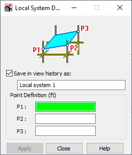
Using this option, you can define the local work plane by:
- clicking View menu > Work in 3D > Local System Definition by 3 Points.
- clicking
 in the toolbar.
After the command is selected, the Local System Definition dialog displays.

If you select Save in view history as, you can specify a name of the defined local work plane determined by coordinates of 3 points. The plane (structure view) is then saved under a given name in the View History dialog. It enables you to return to once defined local plane while working in a structure model.
In the Local System Definition dialog, under Point Definition, you can define the points that determine the local work plane: P1, P2 and P3. The first point (P1) is also the beginning of the local coordinate system.
After you have defined the coordinates of the 3 points, an additional graphical viewer displays, showing the currently designed structure projected on the user-defined work plane. The work plane is marked as LOCAL, below the coordinate system symbol. If you close the dialog before applying your changes, the software returns to the global coordinate system and to the system work plane.