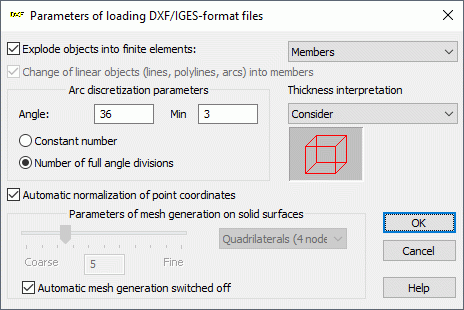
Use this dialog to set the import parameters for *.DXF, *.DWG, and *.IGES files.
Access
- Click
File
 Open Project
 Select a *.DXF, *.DWG, and *.IGES file, and then click
OK.

Explode objects into finite elements
When selected, the elements defined in the DXF file are treated as bars of surface finite elements and you can select from a list of elements: bars, quadrilaterals (4 nodes), quadrilaterals (8 nodes), volumetric elements (8 nodes), or volumetric elements (24 nodes).
When this option is not selected, the elements defined in the DXF file are treated as objects: lines, arcs, contours, and so on. Turning the option off is only recommended for plate or shell structures.
Change linear objects into bars
This option becomes available when the Explode objects into finite elements option is selected. When selected, you can change the linear objects in a *. DXF file into bar elements. Turning the option off, treats lines, polylines, and arcs as objects.
Automatic normalization of point coordinates
If this option is selected the coordinates of some points (such as points on an arc) are slightly rounded up or down when a DXF file is loaded; otherwise, the point coordinates from the DXF file are loaded.
Arc discretization parameters
Angle - Determines the number of elements on the arc that is being defined.
Min - After the Number of full angle divisions is selected, the Min option becomes active, which lets you define the smallest number of full angle divisions. The default value is 3.
Constant number - When selected, the arc is divided into the number of elements defined in the Angle field.
Number of full angle divisions - When selected, the number in Angle refers to the number of full angle (360 degrees) divisions and the Min option becomes active, which lets you define the smallest number of full angle divisions. The default value is 3.
The defined arc is always divided into equal segments. Sometimes, the defined number of full angle divisions does not divide the arc into equal segments. In this case, Robot automatically finds the number of arc divisions that divide the arc into equal segments.
Thickness interpretation
Determines how the thickness of the object is interpreted when opening the file:
- Consider - Object thickness z is considered when opening the file
- Ignore - Object thickness z is not considered when opening the file
- Center - Object thickness z is not considered when opening the file, and the surface is located at the z/2 distance.
When Automatic mesh generation switched off option is selected, the part of the structure that has been generated by a geometrical modeler is not loaded.
After you have finished selecting the import parameters for the *.DXF, *.DWG, and *.IGES files, click OK. The structure is analyzed and the Merge Structure dialog is displayed, where you can define additional parameters for determining the geometry of the structure (structure insertion point and scale).
Groups created from layers
When you import DXF or DWG files with elements assigned to layers then groups are created in Robot Structural Analysis model for each layer, and members are automatically assign to groups based on the layer assignment.
See also:
Correction of Inconsistent Mesh of Volumetric Finite Elements