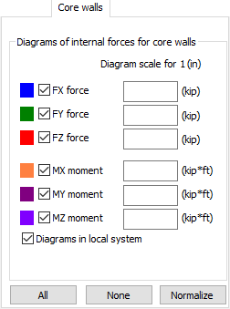
When the Core walls tab is selected on the Diagrams for Core Walls dialog, the following displays:
The core walls in a building model make a group of walls (panels). To define core walls, use the Geometry > Additional attributes > Core walls option.
Grouping the walls in a core wall does not impact the rigidity and the results for a building while the presence of a core wall impacts calculation of the shear center (rigidity) for a story section. The core wall section is considered as a whole. The component of the shear center for a core wall is calculated from the thin-walled member theory.
Additional results can be obtained for the core walls, in form of the reduced forces and moments along the vertical axis of the gravity center of the core wall section.
This dialog displays values for which the diagrams for the core walls will be presented.
- FX force
- FY force
- FZ force
- MX moment
- MY moment
- MZ moment.
For each of the values above, the appropriate color and scale can be selected.
Descriptions of directions (X, Y, Z) for the diagrams of forces and moments refer to the global coordinate system.
The diagrams are presented along the vertical axis cutting through the gravity centers of the core wall section on every story. Two cuts are performed for each story: above the bottom story edge and below the top story edge. Each cut is made at the centroid of the surface elements as shown in the drawing area.
If the stories are not defined, the height of the entire structure is taken in consideration (i.e. there are two cuts in the whole structure).
Forces reduced for each cut at the center of gravity of the core wall cut are determined. Only the forces from the panels belonging to a given core wall are taken in consideration in order to determine the forces and the reduced moments. If a structure contains more than one core wall, reduced forces are calculated for each core wall separately.
The results of the reduced forces for the core walls are also available in the Results / Core walls table.
Select Diagrams in local system, to explore your results in the local axis rather than the global axis.
You can also visualize the local coordinate system for core walls in your drawing. Use the View > Display option and select Local System of core walls under the Classic template.
At the bottom there are the following buttons:
- All - displays the diagrams of all the quantities.
- None - hides all diagrams.
- Normalize - displays the diagram of a selected quantity in such a way that the scale is adjusted to the maximum and minimum value of the highlighted quantity.