We can learn more about how Autodesk Civil 3D creates gradings by looking at some examples of grading intersection. Figure 10 shows the top view of two overlapping gradings. The segment on the left has a gradient of 0%, and the one on the right has a steep gradient of 100% with a crossfall of 2:1.
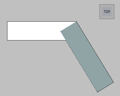
Figure 10: Top view of two intersecting gradings
Figure 11 shows a side view of the gradings, which reveals that they have only a single intersection point. This results in a “chasing gradient” situation between the two segments, without a mathematical intersection line between the two patches, except for the degenerate intersection at the corner point.
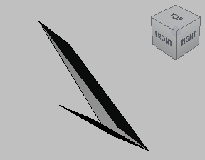
Figure 11: Side view of two intersecting gradings
This example uses exaggerated slopes and gradients to show the problem more clearly, but a similar problem can easily happen any time the slope along the footprint exceeds the crossfall. If two gradings do not intersect, Autodesk Civil 3D handles the problem by averaging the slopes and levels in the intersection zone. This effectively transitions the crossfall in most cases, as shown in figure 12.
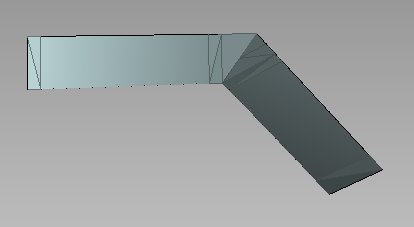
Figure 12: Calculated transition for two intersecting gradings
This situation is very common in real-world grading scenarios. In particular, it occurs when grading to the inside of a footprint where levels of the footprint vary. Similar grading intersection problems can also occur when transitioning around inside corners.