![]()
The Mirror tool also allows you to mirror the current selection about the center of the current coordinate system. You can create a clone with the mirror dialog at the same time. If you mirror a hierarchical linkage, you have the option to mirror the IK limits.

Mirroring an object
The Mirror dialog uses the current reference coordinate system, as reflected in its name. For example, if Reference Coordinate System is set to Local, the dialog is named Mirror: Local Coordinates. There is one exception: If Reference Coordinate System is set to View, Mirror uses Screen coordinates.
As you adjust the various settings in the Mirror dialog, you see the results in the viewports.
Procedures
To mirror an object:
- Make any object selection.
- Do one of the following:
- On the main toolbar, click Mirror.
- From the Tools menu, choose Mirror. If using the Alt menu system, choose Edit menu
 Transform
  Mirror.
3ds Max opens the Mirror dialog.
- Set the mirror parameters in the dialog and click OK.
The active viewport changes to show the effect of each parameter as you set it. When you click OK, 3ds Max creates the choice of mirror that you see previewed.
To make a clone using mirror:
- Make any object selection
- Do one of the following:
- On the main toolbar, click Mirror.
- From the Tools menu, choose Mirror. If using the Alt menu system, choose Edit menu
 Transform
  Mirror.
3ds Max opens the Mirror dialog.
- In the Clone Selection group, choose Copy, Instance, or Reference.
- Make any additional settings as desired and then click OK.
Mirrored Arrays
You can combine the Mirror and Array tools by using them in succession. An entire array can be mirrored, or you can set up mirrored objects before creating an array.
Animating Mirror
When you use Mirror with Auto Key turned on, you see the transition occur as the mirrored object moves into place. For example, a cylinder mirrored to the other side of an axis appears to flatten and reshape itself. The object is, in fact, scaled from 100% to 0% to –100%. This effect is not visible unless the mirror operation is animated.
Mirror Modifier
The Mirror modifier provides a parametric method of mirroring an object or sub-object selection within the modifier stack. You can apply the Mirror modifier to any type of geometry. You can animate the mirror effect by animating the modifier’s gizmo. You can also apply the Mirror modifier by using the Geometry option with the Mirror tool.
Interface

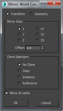
The title bar of the dialog shows the coordinate system currently in use.
- Transform/Geometry
- Determines how Mirror treats the reflected geometry.
- Transform Uses the legacy mirror method, which mirrors any world-space-modifier effects.
- Geometry Applies a Mirror modifier whose transformation matrix matches the current Reference Coordinate System setting.
Note: This option does not mirror any world-space-modifier (WSM) effects. This is suitable if you want the mirrored object to react properly to non-mirrored WSMs.
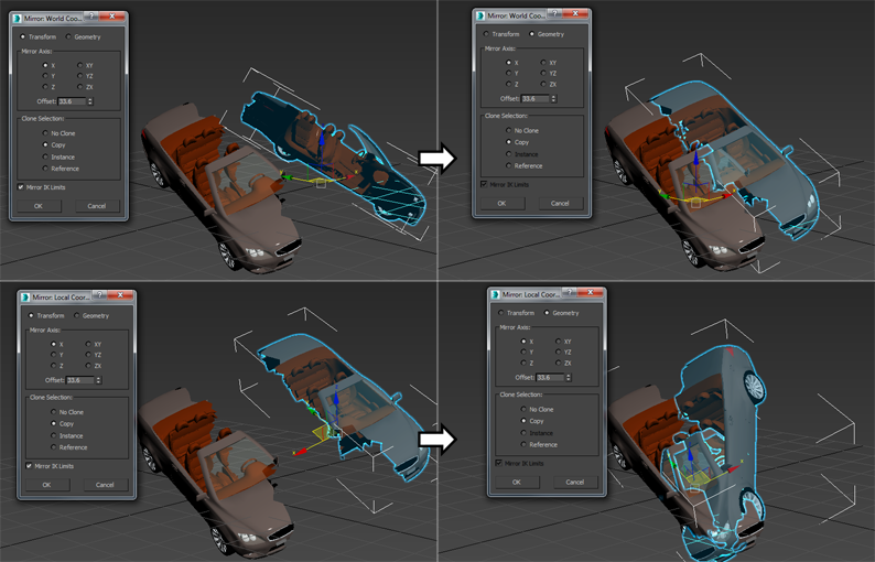
In the following illustration, the car is first mirrored, cloned, and offset in the World coordinate system with the Transform option (top-left) and the Geometry option (top-right). The bottom half of the illustration depicts the same process using the Local coordinate system.

Mirror Axis group
The mirror axis choices are X, Y, Z, XY, XZ, and YZ. Choose one to specify the direction of mirroring. These are equivalent to the option buttons on the Axis Constraints toolbar.
- Offset
-
Specifies the distance of the mirrored object's pivot point from the original object's pivot point.
Clone Selection group
Determines the type of copy made by the Mirror function.
- No Clone (The default.) Mirrors the selected object without making a copy.
- Copy Mirrors a copy of the selected object to the specified position.
- Instance Mirrors an instance of the selected object to the specified position.
- Reference Mirrors a reference of the selected object to the specified position.
If you animate the mirror operation, mirroring generates a Scale key. If you set Offset to a value other than 0.0, mirroring also generates Position keys.
- Mirror IK Limits
-
Causes the IK constraints to be mirrored (along with the geometry) when you mirror the geometry about a single axis. Turn this off if you don't want the IK constraints to be affected by the mirror command.
The end effectors used by the IK are not affected by the Mirror command. To successfully mirror an IK hierarchy, first delete the end effectors: Go to the Motion panel
 IK Controller Parameters rollout
  End Effectors group and, under Position, click the Delete button. After the mirror operation, create the new end effector using the tools on the same panel.