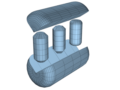
Use ChamferCyl to create a cylinder with beveled or rounded cap edges.

Examples of chamfered cylinders
Procedures
To create a chamfered cylinder:
- From the Create menu, choose Extended Primitives
 Chamfer Cylinder.
 - Drag the mouse to define the radius of the base of the chamfered cylinder.
- Release the mouse button, and then move the mouse vertically to define the height of the cylinder. Click to set the height.
- Move the mouse diagonally to define the width of the fillet, or chamfer (toward the upper left increases the width; toward the lower right decreases it).
- Click to finish the cylinder.
Interface
Creation Method rollout
- Edge
-
Draws the object from edge to edge. You can change the center location by moving the mouse.
- Center
-
Draws the object from the center out.
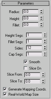
Parameters rollout

- Radius
-
Sets the radius of the chamfered cylinder.
- Height
-
Sets the dimension along the central axis. Negative values create the chamfered cylinder below the construction plane.
- Fillet
-
Chamfers the top and bottom cap edges of the chamfered cylinder. Higher numbers result in a more refined fillet along the cap edge.
- Height Segs
-
Sets the number of divisions along the corresponding axis.
- Fillet Segs
-
Sets the number of segments in the filleted edges of the cylinder. Adding fillet segments curves the edges, producing a filleted cylinder.
- Sides
-
Sets the number of sides around the chamfered cylinder. Higher numbers shade and render as true circles with Smooth on. Lower numbers create regular polygonal objects with Smooth off.
- Cap Segs
-
Sets the number of concentric divisions along the center of the chamfered cylinder's top and bottom
- Smooth
-
Blends the faces of the chamfered cylinder, creating a smooth appearance in rendered views.
- Slice On
-
Enables the Slice function. Default=off.
When you create a slice and then turn off Slice On, the complete chamfered cylinder reappears. You can use this checkbox to switch between the two topologies.
- Slice From, Slice To
-
Sets the number of degrees around the local Z axis from a zero point at the local X axis.
For both settings, positive values move the end of the slice counterclockwise; negative values move it clockwise. Either setting can be made first. When the ends meet, the whole chamfered cylinder reappears.
- Generate Mapping Coords
-
Generates coordinates for applying mapped materials to the chamfered cylinder. Default=on.
- Real-World Map Size
-
Controls the scaling method used for texture mapped materials that are applied to the object. The scaling values are controlled by the Use Real-World Scale settings found in the applied material's Coordinates rollout. Default=off.