Alignments are intelligent shape objects that typically represent the center line of a road, railway, or other linear feature.
Imported alignments are derived from AutoCAD Civil 3D Alignment and Profile combinations only. To import an Alignment, use the Civil 3D Import panel. Layout profiles are automatically associated with imported alignments. Civil View does not support surface profiles (sometimes known as existing ground profiles) or superimposed profiles.
What Are Alignments and Profiles?
Alignments are essentially intelligent shape objects, which are generally constructed from a sequence of tangential geometric entities. There are three basic entity types: arcs, straights, and spirals.
Alignments usually represent the center line or primary longitudinal control line of a road, railway, or other linear designed feature. Alignments are generally designed to conform to local agency-specific design standards where there would normally be a need to adhere to minimum/maximum curve radii, curve length, and super-elevation requirements.
While alignments describe the horizontal path of a shape (visible in a plan or top view), layout profiles are used to describe the vertical path of a shape. Layout profiles (sometimes known as design or finished ground profiles) are similarly constructed from a series of tangential geometric entities, but there are only two basic types: straight grades and vertical curves.
An alignment can have one or more layout profile alternatives associated with it. Alternatively, an alignment could have no associated layout profiles, which results in a shape with a constant elevation on the Z axis.
For a full overview of alignments and profiles, please refer to the AutoCAD Civil 3D User Documentation.
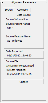
Data Source panel
Displays source information relating to the imported alignment.

Source Information group
- Source Parent Name
- Displays the originating model or site name of the source point collection from which the geometry of this alignment was derived. Typically this is a Civil 3D site name.
- Source Feature Name
- Displays the originating alignment name from which the geometry of this alignment was derived. Typically this is a Civil 3D alignment name.
Date Imported group
The date and time on which this alignment was created from the indicated source file data.
Source File group
- [file name]
- The name and path of the source file from which the alignment was derived.
- File Last Modified
- The date on which the source data file was last updated.
If this date is later than the date on which the object was imported, this would indicate that the selected object might be out of step with your current source design data.
This value is blank if the source file cannot be found.
- Update
- Click to update the alignment from the original source import file. This button is not available if the original source file is no longer found in its original path.
See Civil View Object Updating for further details.
Tip: You can use the Imported Object Manager to update multiple objects simultaneously
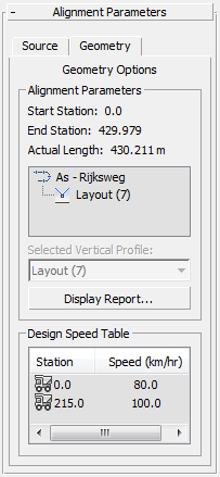
Geometry Options panel
Provides geometric information relating to the entity structure and longitudinal path of the imported alignment and any associated profiles.

Alignment Parameters group
- Start Station
- Station values measure the distance along an alignment at any given point on the shape. The Start Station value shows the applied station value at the first point on the shape.
- End Station
- The End Station value shows the applied station value at the last point on the shape.
- Actual Length
- Shows the actual current length of the alignment.
This value might differ slightly when compared to the difference between the alignment start and end station values. This is because station values are calculated and applied in the source design application prior to export to Civil View, whereas the actual length of the alignment is measured in 3ds Max.
- [alignment structure]
- Provides a hierarchial view of the imported alignment, including any layout profiles associated with it. Where an alignment is related to more than one layout profile, all layout profiles are imported into Civil View but only the first is used.
- Selected Vertical Profile
- Where an alignment contains references to more than one layout profile, this control indicates which layout profile is active.
- Display Report
- Click to generate a detailed report of the imported alignment and layout profile. The report shows coordinate, station, and geometric entity information for every vertex within the selected alignment. This report may be displayed on screen or printed out.
Design Speed Table group
Indicates any station-based design criteria that were applied to the alignment during the design process in Civil 3D. Design criteria can optionally be applied to alignments in Civil 3D in order to check compliance with agency-specific local design standards.