The Symmetry modifier is especially useful when modeling characters or building ships or aircrafts.
This modifier is unique in that it allows you to perform three common modeling tasks:
- Mirror a mesh about the X, Y, or Z plane.
- Slice a mesh, removing parts if necessary.
- Automatically weld vertices along a common seam.

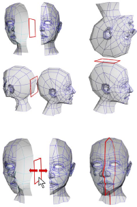
Examples of using Symmetry with different mirror axes or by moving the mirror gizmo
You can apply the Symmetry modifier to any geometry, and you can animate the mirror or slicing effect by animating the modifier's gizmo.
When the Symmetry modifier is applied to a mesh, any edits you make to the original half of the mesh below the Symmetry modifier in the stack also occur interactively to the other half. For an example, see the second procedure, below.
Interface
Modifier Stack

- Mirror
-
The placement of the mirror gizmo delegates how the object will be affected by symmetry. You can move or rotate, as well as animate the gizmo.
For more information on the stack display, see Modifier Stack.
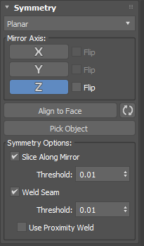
Parameters rollout

- Symmetry Type menu
- Choose the slice type, either Planar or Radial.
Mirror Axis group
- X, Y, Z buttons
- Mirrors the object along the selected axes.
- Flip (Planar type only)
- When enabled, flips the symmetry to the opposite side of the corresponding axis.
- Align to Face button
- Selects the face used to align the gizmo.
 Reset Gizmo button
- Resets the gizmo to its default position.
- Pick Object button
- Selects a reference object from the scene.
Symmetry Options group
- Count (Radial type only)
- Sets the radius of the symmetry.
- Mirror Symmetry (Radial type only)
- When enabled, mirrors half of the geometry to generate clean seams.
- Flip (Radial type only)
- When enabled, flips the mirrored half of the geometry to the opposite side.

Mirror Symmetry with Flip option enabled and disabled
- Slice Along Mirror
- When enabled, causes the mirror gizmo to act as a slice plane when located inside the boundaries of a mesh. When the gizmo is outside the boundaries of a mesh, the symmetrical reflection is still treated as part of the originating mesh. If Slice Along Mirror is disabled, the symmetrical reflection is treated as a separate element of the originating mesh. You can also adjust the Threshold spinner to control the distance of the welded vertices when the mesh is cut. Default=on.
- Weld Seam
- When enabled, automatically welds the vertices along the mirror axis. You can also adjust the Threshold spinner to control the distance of the welded vertices when the mesh is cut. Default=on.
- Proximity Weld
- When enabled, Proximity Weld uses the old method of welding vertices based on proximity. Whereas, the new default method keeps track of the vertices that are generated from the cutting and welds them in a smarter way. Default=off.
Procedures
Example: To apply the Symmetry modifier to an object:
- In the Perspective viewport, create a teapot.
-
 Apply the Symmetry modifier.
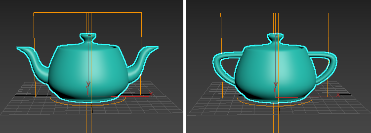
The teapot appears to have two spouts.
- In the modifier stack, click
 (the plus-sign icon) to expand the Symmetry modifier hierarchy, then highlight Mirror.
The mirror gizmo acts as a slice plane when it is within the boundaries of the object
- With Mirror Axis set to X, click and drag the mirror gizmo along the X axis.
Dragging right slices more of the teapot until there is nothing visible. Dragging left causes a second teapot to appear. When the mirror gizmo is moved beyond the boundaries of the original mesh, it acts as a mirror plane showing you two complete teapots.
Example: To perform box modeling with the Symmetry modifier:
- In the Perspective viewort, create a box primitive, and then convert it to Editable Poly or apply the Edit Poly modifier.
- If necessary, press F4 to activate Edged Faces display mode.
-
 Apply the Symmetry modifier.
Other than the new edge loop created by the modifier, the box's appearance doesn't change, because it's already symmetrical.
- On the modifier stack, click
 (the plus-sign icon) to expand the Symmety modifier hierarchy, and then highlight Mirror.
- In the Front viewport, with Mirror Axis set to X,
 move the Mirror gizmo in either direction on the X axis.
Only the left-hand box moves: This is the copy created by the Symmetry modifier.
- Position the Mirror near the left side of the original box, so the two copies are merged.
- On the modifier stack, go to the Edit/Editable Poly level and highlight the Vertex sub-object level.
If you no longer see the Symmetry copy of the box, turn on
 (Show End Result On/Off Toggle).
With Show End Result on, you might see an orange wireframe “cage” that shows the edges of original object. This is on by default for editable poly objects, but off by default for the Edit Poly modifier. The Show Cage toggle for editable poly objects is on the Subdivision Surface rollout, and for Edit Poly it's on the Edit Poly Mode rollout.
You can also see that only the vertices of the original object are visible; the vertices of the symmetry object can't be transformed directly.
-
 Move one of the visible vertices on the right side of the box.
As you do so, its counterpart on the symmetry object moves symmetrically in real time.
As you can see, the Symmetry modifier not only creates a mirror image of an object for you, but also lets you manipulate both sides in tandem in an intuitive way.
- Now
 move one of the vertices on the left side of the box, where it overlaps the symmetry box.
Because you're also moving its counterpart vertex, which is invisible, the apparent result is motion of the corresponding point on the plane of symmetry. This isn't as intuitive as moving a non-overlapping point, so for best results, position the Mirror gizmo so as to cause as little overlap as possible; that way you can edit the center vertices directly on the plane of symmetry.