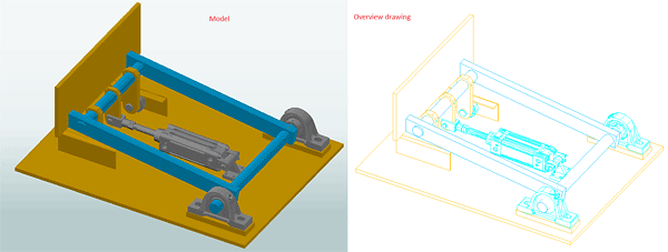
Many manufacturers of parts, from the mechanical and hydraulic industry, offer for download, on their official web sites, dwg files which contain 3D solid components. Those solids are used on modeling, in other specialized programs, for an accurate positioning of the mounting holes and to display possible collisions caused by the dimensions of the component.
In Advance Steel the 3D solids can be imported as special parts and can receive, by the automatic numbering, the manufacturer's article number, also can be displayed in the BOM lists and can be detailed using overview drawing styles.

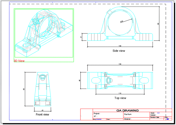
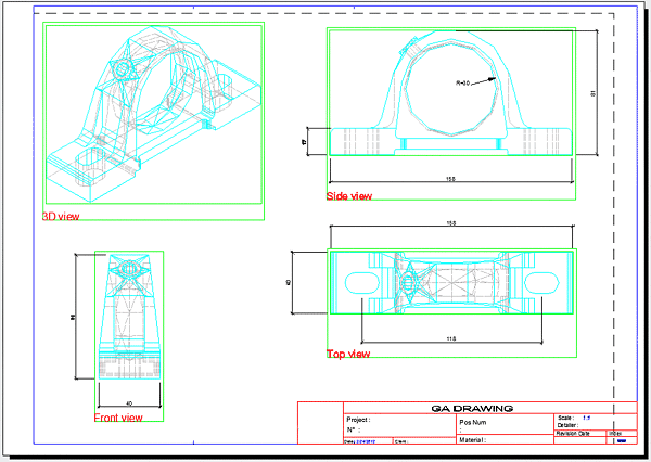
There are two methods for creating single part drawings for special parts:
- Using the AutoCAD "flatshot" command
- Using multiple times an overview drawing style
Creating single part drawings for special parts using the AutoCAD "flatshot" command
This command projects all edges of 3D solids, surfaces and meshes on a plane parallel with the viewing plane. The projected image is created in a block and is placed in the XY plane of the UCS.

The command provides the option to show the hidden lines and also the tangential edges. You can select between different linetypes and colors for the visible and hidden lines. In the above figure the visible lines are set to Continuous with byBlock color and the hidden lines are set to Dash with Red color.
To create the single part drawing, perform the following steps:
- Select an overview drawing style, which uses selection, and create a 3D view for the special part, on a prototype which will give you enough space for the 2D blocks you will copy later.
- Open the special part drawing from where it is saved (Advance Steel special parts are saved by default in ...\ProgramData\Autodesk\Advance Steel 2023\[INSTALLATION LANGUAGE EXTENSION]\Shared\Support\Symbols) or copy the special part from the model into another drawing.
- Create the 2D block views that you want to detail (Top, Side or Front) using the "flatshot" command. You can synchronize the 2D block linetype and color with the drawing style's representation (used at point 1).
Example: If the drawing styles representation uses for visible lines a continuous linetype with cyan color and for hidden lines a dash linetype with grey color then you can select the same linetypes and colors in the "flatshot" command window.
- Copy the 2D blocks in the 3D view detail drawing created at point 1.
- Add the necessary dimensions and text to the 2D views of the special part and then save the detail drawing.
The only dimensions that you can add to these 2D views are the CAD platform ones; this is because Advance Steel manual dimensions need a view selection when created.

The 2D blocks including the manually added CAD dimensions can be saved, in another drawing, and reused.
Creating single part drawings for special parts, using multiple times an overview drawing style
To create a single part drawing using multiple times an overview drawing style, perform the following steps:
- Rotate the UCS so that when you look from the Z axis you see the Top, Side or Front of the special part.
- Pick an overview drawing style which uses selection and create the view of the special part. Assign the view an informative title.
- Repeat steps 1 and 2 until you created all the views you need.
- Open the detail and add the necessary dimensions. You can use Advance Steel's dimensions. Next, save the drawing.

An advantage of using this method is the fact that Advance Steel dimensions can be used. The measurements of these dimensions are in accordance with the scale used by the view.