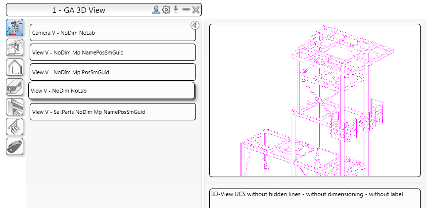
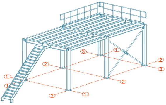
Save the model before you start creating drawings.
The viewport of the created view depends on the active user coordinate system (UCS). The view direction is against the Z-direction of the UCS.
- To create an isometric view, click
 (UCS View), on the
UCS tool palette and place the UCS in the plane of the screen.
- On the Output tab
 Documents panel, click Drawing Styles. The Drawing Styles palette opens.
- Select the desired drawing style and click
Use

- In the Drawing type dialog change the scale to 1:50.
- Click OK.
- In the Select destination file dialog, set a path for a separate DWG in which the detail is placed.
- Select the prototype template.
- Click OK.
The drawing is created and saved as in a DWG format, in the specified path.
