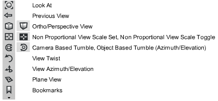
Use the ViewCube tool and NavBar
Autodesk® ViewCube® navigation tool and NavBar provide the same viewing functionality found in the View Panel.
Use the ViewCube and NavBar view control
You can use the ViewCube tool and NavBar, or the View Panel to control your view, or you can choose to use neither.
Select the ViewCube and NavBar as the view control
- Choose Preferences > General Preferences
 .
. - Click Viewing and set the View Control option to ViewCube, View Panel, or None.
Display the ViewCube and NavBar
- With ViewCube selected as the View Control, press
 + .
+ . .
.
Make the ViewCube active
- With ViewCube selected as the View Control, move your pointer over the ViewCube. The top right corner is the default ViewCube location. You can change the location to the top or bottom, left or right corner.
Reorient the view with ViewCube
Use ViewCube to reorient the current view of a model. You can reorient the view with the ViewCube tool by clicking predefined areas to set a preset view as current, click and drag to freely change the view angle of the model, and define and restore the Home view.
Switch to a preset view
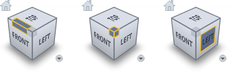
Click one of the edges, corners, or faces on the ViewCube tool to reorient the view to a preset location.
The ViewCube tool provides twenty-six defined areas you can click to change the current view of a model. The twenty-six defined areas are categorized into three groups: edge, corner, and face. Of the twenty-six defined areas, six of the areas represent standard orthogonal views of a model: top, bottom, front, back, left, and right. Orthogonal views are set by clicking one of the faces on the ViewCube tool.
Use the other twenty defined areas to access angled views of a model. Clicking one of the corners on the ViewCube tool reorients the current view of the model to a three-quarter view, based on a viewpoint defined by three sides of the model. Clicking one of the edges reorients the view of the model to a half view based on two sides of the model.
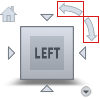
Roll a face view
When you view a model from one of the face views, two roll arrow buttons display near the ViewCube tool. Use the roll arrows to rotate the current view 90 degrees clockwise or counterclockwise around the center of the view.
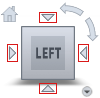
Switch to an adjacent face
When the ViewCube tool is active while viewing a model from one of the face views, four orthogonal triangles display near the ViewCube tool. Click the triangles to switch to one of the adjacent face views.
Switch face views with the arrow keys
When you view a model from one of the face views, you can use Shift + Alt + [Arrow Key] to rotate the face view to the next position.
Note for versions of Autodesk Alias 2019.2 and later
The following options are available only with Autodesk Alias 2019.2 or later.
- Shift + Alt + Right/Left: Rotate the ViewCube to the right/left.
- Shift + Alt + Up: View the Top surface of the ViewCube. To return to one of the side views, use Shift + Alt + Up again, or Shift + Alt + Right/Left.
- Shift + Alt + Down: View the Bottom surface of the ViewCube. To return to one of the side views, use Shift + Alt + Down again, or Shift + Alt + Right/Left.
Switch to a custom view
To interactively reorient the view to a custom viewpoint, click the ViewCube tool, hold down the  , and drag in the direction that you want to orbit the model.
As you drag, the cursor changes to indicate that you are reorienting the current view of the model. If you drag the ViewCube tool close to one of the preset orientations and it is set to snap to the closest view, the ViewCube tool rotates to the closest preset orientation.
To indicate that you are in a true orthographic planar or elevation view, the faces of ViewCube are highlighted green by default. You can change this color in Preferences > Interface > User Colors. Under Modeling Window Colors set the ViewCube Axis Ortho color.
Define and restore the Home view
The Home view is a special view stored with a model that makes it easy to return to a known or familiar view. You can define any view of the model as the Home view.
The default Home position is the existing orientation of the default 3D view.
- To define the Home view, click the context menu button located below the ViewCube tool, and click Set Current View as Home.
- To apply the saved Home view, click the Home button (
 ) above the ViewCube tool.
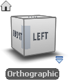
Set the view projection mode
To change the view projection mode, click the context menu button located below the ViewCube tool, and click one of the following options:
- Orthographic – Switches the current view to orthographic projection.
- Perspective – Switches the current view to perspective projection.
- Perspective with Ortho Faces – Switches the current view to perspective projection unless the current view aligns with a face view defined on the ViewCube tool, in which case it switches the view to orthographic projection.
When the view is set to an orthographic projection, a label below the ViewCube indicates this.
Control the appearance and behavior of the ViewCube tool
The ViewCube tool displays in one of two states: inactive and active. When the ViewCube tool is inactive, it appears partially transparent by default so that it does not obscure the view of the model. When active, it is opaque and may obscure the view of the objects in the current view of the model.
In addition to controlling the inactive opacity level of the ViewCube tool, you can also control the size and position of the tool:
Control the appearance of the ViewCube tool
- Click the context menu button located below the ViewCube tool, and click Options.
- Set the available options:
On-screen position
Place the ViewCube in any corner of the screen by selecting one of these options: Top Right, Bottom Right, Top Left, or Bottom Left.
ViewCube size
Set the ViewCube size to Automatic, Tiny, Small, Normal, or Large.
Inactive opacity
When the cursor is in the vicinity of the ViewCube, the cube and all the additional controls are displayed, fully opaque. However, when the cursor is distant from the ViewCube, the additional controls (except the Home button) do not display; the ViewCube and the Home button may display at reduced opacity. Set the opacity display when the cursor is distant (inactive) from the ViewCube.
Keep scene upright
Select this option to maintain the up direction of the scene.
Snap to the closest view
While being dragged, the ViewCube and the model rotate. If Snap to closest view is selected, the viewpoint will snap to one of the fixed views when it is angularly close to one of the fixed views.
Display the NavBar
The NavBar is available for use when the ViewCube is selected as the View control in the Viewing section of Preferences > General Preferences . To display the NavBar, press + ..