Create a fillet surface
![]()
Fillets create a transition surface between two surfaces or sets of surfaces. Fillets create a transition surface between two surfaces or sets of surfaces.
Fillets are typically used to build balanced blends between the primary surfaces of a design. Small detail fillets can also be built, but the Round tool should also be considered as it will calculate a corner blend where three or more edges come to one point. (For more information, see Create rounded edges and corners).
Fillet surface can be automatically trimmed to create a continuous flow of surfaces.
Access the Surface Fillet tool settings by clicking the Surface Fillet tool  icon, then the
  icon.
icon.
Create a fillet surface between existing surfaces
When creating a fillet surface you will:
- Select inputs for the surface fillet
- Choose the fillet quadrant
- Choose the Construction Type
- Specify fillet size with Form Factor
- Specify Interior Flow Control.
Select inputs for the surface fillet
The fillet surface will be built between two surfaces, or two surface sets which are G1 Tangent continuous. These can be chosen with a box-select or with individual selection.
Input Set 1 displays with pink boundaries. Input Set 2 displays with yellow boundaries. It doesn't matter which set is pink or yellow as they are treated the same.
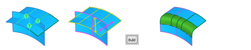
Choosing Fillet Quadrant
Pink and Yellow arrows are displayed to choose the resulting position of the fillet. In most cases, the tools direct the arrows on the correct side, but if you need to change them, click either arrow to change the direction before selecting the Build button.
Query Edit does not re-invoke the arrows. This means that the directions cannot be changed after the fillet has been built. In this case, undo the fillet, correct the arrow directions, and then click the Build button.
Surfaces can be added or removed before clicking the Build button or the Update button. Additional surfaces are added to whichever input set they are G1 Tangent continuous. The Selection Options settings for mouse button behavior are respected. For example, by default use RMB to remove and LMB or MMB to add.
Surfaces displayed with white boundaries are non-G1 continuous with either of the Input Sets. This may indicate a surface selected in error, or it may be intentional when creating fillet surfaces using multiple input surfaces, indicating Input Set 3 (see below).
Specify Fillet Size with Form Factor
When you use G1 Tangent, G2 Curvature, or G3 Curvature as the Section Type, a Form Factor value is added, which lets you specify the Fillet Size.
Specify the Centre Radius value when you want to maintain a constant peak radius, while adjusting the length of the lead-in using the Form Factor. The contact lines change as the Form Factor is modified.
Specify the Tangent Offset, Chordal Length or Tangent Length when you want to maintain constant contact lines for the fillet, while adjusting the shape using the Form Factor. The peak radius changes as the Form Factor is modified.
Specify Interior Flow Control options
![]()
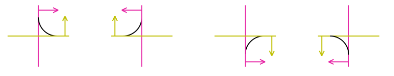
In most cases, Auto provides optimal results for Start, Internal, and End Flow Control. For Interior Flow Control, Alias can use different methods along the interior length of fillet to produce the best results based on the topology of the input surface sets. Selecting User Defined displays manipulators that indicate the Flow Control method used at each point along the constructed fillet where the input surfaces connect.
There are three different boundary conditions that allow different groups of methods to be selected:
![]() T-junction with no other corresponding boundary on the other side.
T-junction with no other corresponding boundary on the other side.
![]() Two T-junctions on opposite sides, which are:
Two T-junctions on opposite sides, which are:
- Close to each other.
- Linked and form a single boundary in the fillet group.
![]() Two T-junctions on opposite sides, which are:
Two T-junctions on opposite sides, which are:
- Close to each other.
- Unlinked by the T-Align method.
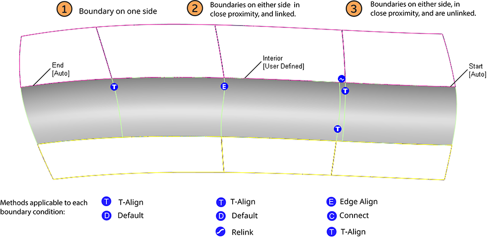
Select User Defined, and then click the manipulators to cycle through the methods that are applicable to each boundary condition. If Auto Update is on, that interior section of the fillet gets rebuilt with the selected method. This lets you quickly experiment with the boundaries and the CV layout of the fillet.
If Surface Type is set to Multiple surfaces and curves-on-surface are created at the edges of the fillets (see Trim Type) those curves-on-surface are segmented to correspond to the multiple fillet surface boundaries. To create the curves-on-surface as a single piece (for each surface), set Surface Type to Single surface
Create fillet surfaces using multiple input surfaces
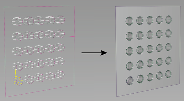
In the Surfaces tool palette, select the Multi-Surface Fillet > Surface Fillet tool
, then the icon.Adjust settings in the Surface Fillet Control window.
Select the slab surface and then select all the input surfaces. (Either box pick with the initial position on one of the slab surfaces, and then select all of the surfaces, or select one element of the slab surface set, and then using the middle mouse button, box select additional surfaces until all are selected.)
Note:After selecting the input surfaces, the second input set displays yellow and the third input set displays white.
Click Build.
To rework the results, use Query Edit.
Create a fillet surface between surface curves
Freeform blend lets you create a fillet between surface curves (surface boundaries, trim edges, isoparametric curves, or curves-on-surface.
In other words, you use surface curves on the two sets of surfaces to define the contact lines at the ends of the fillet.
You can also select free curves. If a contact line is made up entirely of free curves, that side reverts to G0 Position continuity. As well, Edge align is not possible on that side. If a contact line is made up of both free curves and surface curves, then up to G1 Tangent continuity is allowed on that side. You can only attempt Edge align for the surface curve sections.
In the Surfaces tool palette, select the Multi-Surface Blend > Freeform Blend tool
 , then the icon.
Click surface curves on the first set of surfaces to define the contact line.
The first set of curves is highlighted in purple.
Note:If Chain Pick is turned on in the option window, selecting the boundary of one surface will also select all other boundaries that are tangent continuous with it.
Repeat for the second surface or set of surfaces.
The second set of curves is highlighted in yellow.
Click the Update button.
(This is not necessary if Auto Update is turned on in the option window.)
What if...?
The fillet surface will not build?
Try lowering the fillet radius. Often the fillet does not build simply because there is not enough room to create the radius set in the options.
I don’t want to trim the surfaces back?
The default is to automatically trim the surfaces back to the new fillet surface. Use the Trim Type option in the control window to have the fillet tool only create curves-on-surface (but not trim), or turn trimming off completely.
Related Tasks
- Choose the type of a fillet surface
- Control the radius along the length of a variable fillet surface
- Control the chordal length along a variable fillet surface
- Manipulate fillet surface cross section and continuity
- Troubleshooting trimmed surfaces