Surfaces > Revolve
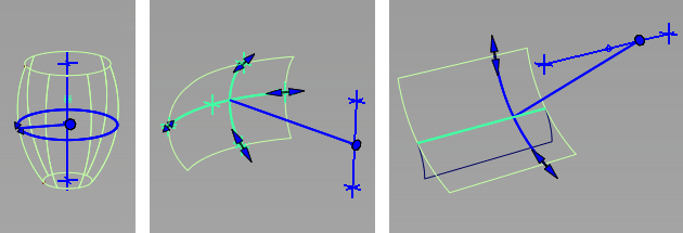
Creates a surface of revolution by sweeping curves around an axis, sweeping an arc along an arc of revolution, or sweeping curves along an arc of revolution. The last two methods are useful for creating vehicle side windows.

Revolve Control
Surface type
Specifies the type of surface you are building:
Freeform – Creates a surface by sweeping a curve, isoparametric curve, curve on surface, or trim boundary around an axis, creating an effect similar to that of a lathe. This is the standard surface of revolution, and is also the default.
Side Glass – Displays the Mode option.
Mode
Specifies the type of side glass you are building:
Barrel – Creates a section of a surface of revolution through the specification of five points that define an arc of revolution and an intersecting arc, the barrel curve. This type of surface is useful for modeling vehicle side windows.
Helix – Creates a section of a surface of revolution through the specification of one or more curves, and two points that define an intersecting arc of revolution. This type of surface is useful for modeling vehicle side windows.
Sweep Angle
The angle of revolution (in the current angular units). After creating the surface, you can also change this angle by using the manipulator handles.
This option only appears if Surface type is set to Freeform.
Per Segment
Specify the sweep angle per segment. If the sweep angle per segment does not divide equally into the total sweep angle then the last surface will be a smaller surface containing the remainder.
This option only appears if Surface type is set to Freeform.
Segments
Lets you specify the number of individual surfaces that will form the revolution. The surfaces each have the same sweep angle, are grouped, and curvature continuous with each other.
Degree
The degree in the V direction of the new surface, from 1 to 7, with 5 being the default.
Spans
The number of spans in each segment of the revolved surface.
For sweeps of 360 degrees, 6 - 8 sections is usually sufficient. Using more than 12 section is not recommended and generally does not improve the surface.
Curve degree
Specifies the degree of the barrel curve (the second arc), which becomes the degree of the barrel surface in the U direction.
This option is only available when Surface type is set to Barrel.
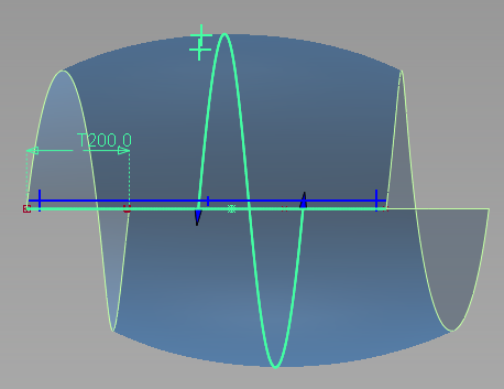
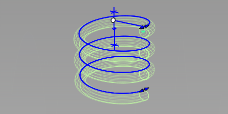
Pitch
Specifies the displacement of the curves (along the axis) over one complete revolution.
This option is only available when Surface type is set to Freeform or Side Glass in Helix mode.

Helix, Pitch of 200.0

Freeform, Pitch of 200.0
Axis Options
Axes
This option only appears if Surface type is set to Freeform.
Local – Revolve around the object’s (or group’s) pivot point and local axes.
Only one curve or group of curves can be selected when using Local mode. Group the objects to revolve them around the rotation pivot and local axes of the group, or use Global mode.
Global – Revolve around the global (world) axes, or the origin and axes of the current construction plane.
In this mode, you can select several ungrouped curves, individually, or by box selection, either before or after entering the tool.
X, Y, Z
Revolves around the X, Y, or Z, axis (either Local or Global).
After creating the surface, you can move and rotate this axis using the manipulator handles.
Picked
Revolves around a picked vector object. You can also enter the vector object's name in the Picked Vector field.
Manip
This option is set automatically when you use the manipulator handles to modify the axis of revolution.
Refresh Vector
This button appears only if X, Y or Z is selected. Click it to update the vector if the axis has been modified.
Retain Vector
Click this button to create a vector object corresponding to the axis of revolution in the view windows.
This button does not appear when the Picked option is selected.
Create Vector
Click this button to create a vector to use as the revolve axis.
Click in the view to place the start of the axis, or type the position and press  . Use the vector manipulator to position the vector and click Accept.
Angles
Start angle/End angle
Specify the angle between the start/end points of the arc of revolution and the barrel or helix curve. These values are also controlled by arrow manipulators on the model.
These options only apply to Barrel and Helix surfaces.
Curve start angle/Curve end angle
Specify the angle between the start/end points of the barrel curve and the arc of revolution. These values modify the extent of the curve. They are also controlled by arrow manipulators on the model.
These options only apply to Barrel surfaces.
Control Options
Auto Update
Turn on this option to have the new surface automatically re-calculated and displayed as you modify the option values or make adjustments to the manipulators.
If it is off, you must click the Update button in the option window to update the surface.
Create History
Save the history of the new surface for later editing. If you turn Create History on, when you modify the curve that was revolved to create a surface, the surface updates. You can also bring back the manipulator handles for further editing.
Continuity Check
Turn on this option to confirm curvature continuity between the individual surfaces when Segments is greater than 1. You should see green locators marked "C" between the surface segments.
If you are building degree 1 (polygonal) surfaces , then a yellow "T" will indicate tangent breaks between the surfaces.
Chain Select
If this box is checked, selecting a curve also selects all other curves that are tangent continuous with it.
This option does not appear when Surface type is set to Barrel.
Create Metadata
Specifies whether or not the Revolve tool creates history metadata.Note: The Create Metadata option is available only with Autodesk Alias 2019.2 or later.
Buttons
Update
When Auto Update is turned off, use this button to re-calculate and re-display the surfaces after modifying the options.
Undo All
Deletes the revolved surfaces and de-selects the input curves so you can make new selections.
Next
De-selects everything and re-invokes the tool.
All the curves selected within the same invocation of the tool belong to a single history command and can be modified simultaneously when the Revolve tool is re-entered through Query Edit.