Surfaces > Multi-Surface Fillet > Surface Fillet
![]()
Builds a fillet surface between two sets of surfaces. These can be automatically trimmed to create a continuous flow of surfaces.
It is typically used to build balanced blends between the primary surfaces of a design. Small detail fillets can also be built, but the Round tool should also be considered as it will calculate a corner blend where three or more edges come to one point.
Surface Fillet Control options
Surface fillet terminology
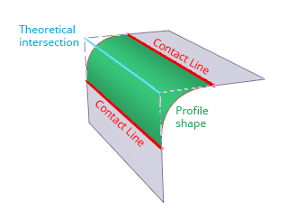
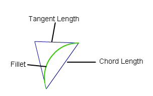
The terms used to describe features of a Surface Fillet are shown below:
Construction Type
The Construction type defines whether the fillet is specified by a profile shape or a width value determining the position of the contact lines.
Radius – Specifies a profile shape. This type uses a 'rolling-ball fillet' construction specified by a Radius value, or a Center radius and Tangent offset value for non-circular fillets.
![]()
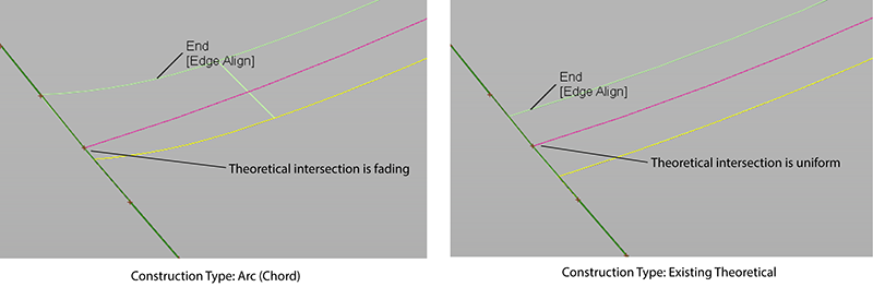
Arc (Chord) – Controls the width between the contact lines and creates a symmetrical arc type of fillet. The fillet's theoretical intersection may differ from the true theoretical intersection of the input surface sets. Use the Chordal Length (or Tangent Length) option to set width of the fillet.
For input surfaces that are tangential at any point, Build Theoretical or Existing Theoretical typically provide better results. When Arc (Chord) is used in this case, the theoretical intersection can fade, which causes a poorly constructed fillet.
If you load a file that uses Chord as a Construction Type from a previous version of Alias, Arc (Chordal) may produce a different result in Alias 2023.1. In this case, choose the Construction Type option that produces the best results.
![]()
Existing Theoretical - Controls the width between the contact lines. This type uses the true theoretical intersection of the input surfaces to build the fillet.
![]()
Build Theoretical - Controls the width between the contact lines. This type generates a theoretical intersection using an offset method when an existing theoretical intersection is missing. This method works well in situations when the input surfaces are not trimmed to the theoretical intersection or do not touch the theoretical intersection.
Section Type
Controls the shape of the fillet’s cross-section by imposing different continuity levels with the input surfaces on each side.
G0 Chamfer – Creates a chamfer edge between the two sets of surfaces. This type maintains only position continuity with the surfaces on either side.
G1 Circular – Creates a fillet with circular cross-section, tangent to both sets of surfaces. This type maintains tangent continuity with the surfaces on either side.
G2 Curvature – Maintains curvature continuity (G2) with both sets of surfaces. G2 continuity means that the curvature (which is the inverse of the radius of curvature) is the same on both sides across the fillet’s boundaries.
G3 Curvature – Maintains G3 continuity with both sets of surfaces. G3 continuity means that the curvature’s rate of change is the same on both sides across the fillet’s boundaries.
When calculating the fillet, the V degree is adjusted so that the surface has enough CVs to provide the required continuity on both sides. Degree 5 is needed for G2 Curvature and degree 7 is needed for G3 Curvature.
G2 Curvature/Arc – Creates a fillet that has a short lead-in with curvature. This type maintains a true arc-shaped section between the two sets of surfaces. Use the Lead-in control to adjust the length of the lead-in. The Auto Adjust Sliders toggle automatically sets the Form Factor and Arc Range values to produce the optimal shape as you adjust the Lead-In value.
Bias – Creates a fillet with a peak radius and tangent offset, the center of which is biased toward (closer to) one set of surfaces.
Lead – Creates a fillet with a peak radius and tangent offset that define the point of contact with the input surfaces. This type maintains tangent continuity with the surfaces on either side.
Bias Factor
Moves the center rail of the fillet surface closer to one side. A value of 0 is centered. Negative values bias toward the first set of surfaces. Positive values bias toward the second set of surfaces.
This option is only available when Section Type is Bias.
Curvature
This option is only available when the Section Type option is set to Bias , G2 Curvature or G3 Curvature.
None – Do not maintain curvature continuity.
Side 1, Side 2 – Make the fillet surface curvature continuous with the first or second set of surfaces.
Both: Make the fillet surface curvature continuous with both sets of surfaces.
Variable Fillets
If this option is checked, you can set the radius or chordal length/tangent length at different points along the length of the fillet.
Radius, distance, and surface controls
Specify
This option and its related parameters are only visible if Construction Type is Radius.
For Bias and Lead section types, choose whether you want to specify the Peak Radius or the Knee Ratio.
For G1 Circular, G2 Curvature, and G3 Curvature section types, choose whether you want to specify the Center Radius, the Tangent Offset, or Both. Those values offer different ways of specifying the peak/center radius and/or lead distance.
The lead distance expresses how much a fillet extends into the adjacent slab surfaces. A longer lead distance provides a smoother transition and better continuity.
If Specify is set to Center radius or Tangent offset, and you also set the Form Factor, the third parameter (either Tangent offset or Center radius) varies along the fillet. Both lets you specify both the Tangent Offset and Center Radius of the fillet, but not the Form Factor. The form factor is calculated automatically from these two values and varies along the fillet.
Default Profile Radius/Center Radius/Peak Radius
The Peak Radius slider appears only when Section Type is Bias or Lead, and Specify is set to Peak Radius. The peak radius is the minimum radius that the fillet is allowed to have at the top.
The Center Radius slider appears only when Section Type is G1 Circular, G2 Curvature, or G3 Curvature, and Specify is set to Center Radius. The center radius is the radius at the arclength center of the fillet.
If Variable Fillets is checked on, the Specify option becomes unavailable. You can only specify tangent offsets, not center radii.
Auto Adjust Sliders
(Appears for the G2 Curvature/Arc Section Type only.) Automatically sets the Form Factor and Arc Range values to produce the optimal shape as you adjust the Lead-In value. This lets you quickly arrive at the optimal fillet shape and curvature comb without constant adjustment of these three settings.
If you turn off Auto Adjust Sliders, be aware that setting Lead-In, Form Factor, and Arc Range values independently can create undesirable section shapes. For best results in this case, use a Curvature locator (Locators > Curvature > Curvature) to ensure the curvature of the fillets meets the desired shape.
Lead-In
(Appears for the G2 Curvature/Arc Section Type only.) Sets the length of the fillet lead-in. For best results, turn on Auto Adjust Sliders while adjusting this value.
Tangent Offset/Default Tangent Offset
Radius of a sphere that is tangent to both input surfaces at the endpoints (that is, contact points) of a given U-isoparm on the fillet.
When Variable Fillets is checked on, Default Tangent Offset is the initial tangent offset along the whole length of the fillet. You then add manipulators at various points along the fillet and specify different tangent offset values.
This option is only available when Construction Type is Radius.
Knee Ratio
This is the ratio between Peak Radius and Tangent Offset, that is Knee Ratio = Peak Radius / Tangent Offset.
It is only available when Section Type is Bias or Lead.
Form Factor
This parameter lets you adjust the shape of the fillet. It specifies the ratio between the lengths of the innermost and outermost CV arms of the hull in the V direction of the fillet. Values range from 0.1 to 2.0. The smaller the value, the sharper the bend in the fillet.
This option is only available when Section Type is G1 Circular, G2 Curvature, or G3 Curvature.
A G2 fillet with, left: form factor = 0.1, and right: form factor = 2.0.
Chordal Type
Chordal length – a chordal length is specified in the field below.
Tangent length – a tangent length is specified in the field below.
This option is only available when Construction Type is Chord.
Chordal Length/Tangent Length
The distance to maintain between the two sides of the fillet, or the length of the tangent segment (see picture above).
This option is only available when Construction Type is Chord.
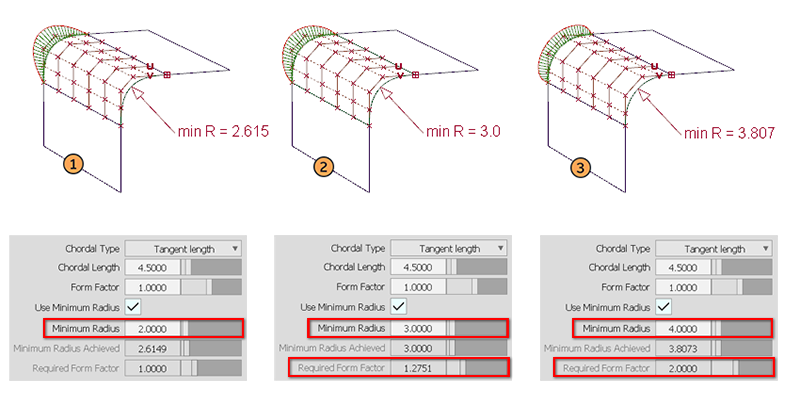
Use Minimum Radius
This option appears when the fillet width is specified using Construction Type: Arc (Chord), Existing Theoretical or Build Theoretical. With these Construction Types, you cannot explicitly set a radius value.
The Use minimum Radius option checks that no part of the fillet surface falls below a set value, and if it does, adjusts the Required Form Factor to modify the fillet profile to ensure the Minimum Radius value is not violated. This is typically needed for safety or legislative requirements.
There are three potential outcomes, with the read-only fields giving information on the results:
- If the fillet does not create any part of its surface with a radius less than the Minimum Radius value, then the result is the same as if Use Minimum radius had not been selected.
- If modification is required, the two read-only fields provide information on how the Form Factor has been modified to achieve the required minimum radius.
- If a Required Form Factor greater than 2 would be needed to achieve the required minimum radius, then it won't be achieved and the the actual minimum radius is displayed. In this case you would need to increase the chordal or tangent Length value of the surface fillet to achieve the desired minimum radius.
Crown Mode
For G0 Chamfer section type only. This option lets you raise or lower the midpoint of the surface between two input curve sets using a crown. Choose between adding a Proportional Crown or an Absolute Crown. This option is not available when more than two curve sets are selected.
You can also switch between the crown modes using the in-canvas manipulator. Click below the Crown label and choose between Proportional Crown, Absolute Crown, or Off.
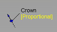
Proportional Crown
Select this option to create a crown that is proportional to the distance between the curves. This setting makes the surface degree 2 with a single row of CVs in the center.
Absolute Crown
Select this option to create a crown that has a consistent height across the section regardless of the section width or distance between the curves.
Crown Mode is set to off when you load a WIRE file that includes history results for Absolute Crown into versions previous to Alias 2022.2 Update.
Crown Flip
Flips the direction of the crown.
Click the arrow on the crown manipulator to flip the crown direction directly on the model.
Crown Value
Controls the height of the crown.
Proportional Crown Value - The value corresponds to a percentage of the distance between the two rails. The slider ranges from 0.0 to 0.1, but larger values can be entered into the field.
Absolute Crown Value - Sets the crown height to an absolute value based on the set measurement units. The slider ranges from 1 to 10, but larger values can be entered into the field.
To change the Crown Value using the in-canvas manipulate, drag the arrow. The value adjusts in 0.005 increments. Use the left mouse button for adjustments, the middle mouse button for fine adjustments.
Crown Shape
Increase the degree of the surface from 2 to 3, giving two central rows of CVs. Shape values less than 1 move these CVs closer to the edges of the surface, positive values move them closer to the center.
Crown Position
Controls the U direction of the crown shape from the middle of the fillet surface toward either input surface. When set to 0, the crown shape is at the middle of the fillet surface. Increasing or decreasing this value moves the crown shape towards either input surface. Crown Shape must be set to a value greater than 0 before Crown Position has any effect.
Explicit Control
Gives you controls of the surface degree(s) and maximum number of spans in the new fillet surface.
Explicit Control Options
These options are only available when Explicit Control is turned on.
(Length) U Degree
The degree of the new fillet surface in the U direction (that is, along the surface edges). Enter a whole number from 2 to 9.
(Section) V Degree
The degree of the new fillet surface in the V direction (that is, from one rail to the other).
This option is only available when Section Type is set to G1 Circular (values range from 3 to 6) or G2 Curvature (values range from 5 to 7).
G3 Curvature does not provide a V Degree slider, but keeps the V degree set to 7 as required by G3 transitions.
Max. Spans
If Surface Type is set to Multiple surfaces, this value specifies the maximum number of spans for each fillet surface. If Surface Type is set to Single surface, it specifies the maximum number of spans inside each pair of boundaries between the original surfaces.
This option is only available when Explicit Control is checked, and neither Bezier Surfaces nor Uniform Spans is checked.
Uniform Spans
Controls the number of spans for each fillet surface.
Maximum Spans/Deg uses the specified number of spans or less, if it achieves continuity, and reduces the degree of the surfaces if the continuity can be achieved with a simpler surface. Higher degree is used for areas of high curvature, and lower degree for less complex shapes.
Maximum uses the specified number of spans or less, if it achieves continuity.
Explicit uses the exact number of specified spans, regardless of whether continuity is achieved with a lesser number of spans.
Spans
Appears when Maximum or Explicit are selected. Lets you specify the number of spans of equal length for each fillet surface. If Bezier Surfaces is also on, then a corresponding number of Bézier patches of equal lengths is created.
Flow Control
![]()
Start/Interior/End
Controls how the fillet surface(s) edges (in the V direction) meet up with the edges of the boundary surfaces. The options can be changed using the in-canvas manipulators or the Control window settings.
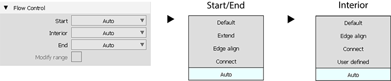
Auto
![]()
Automatically chooses the best option for each setting based on the input geometry. Auto is the default setting.
The Interior setting for Flow Control has an additional User Defined option that appears when there are interior boundaries in the input surface sets. This lets you view the flow settings that Auto used at each interior boundary. See User Defined.
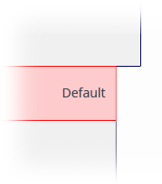
Default
The edges of the fillet surfaces meet the start and/or end points of the boundaries at a 90 degree angle.
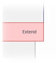
Extend
The fillet is extended so that it reaches to the end of the longest boundary surface, at its start and/or end.
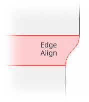
Edge align
The tool tries to colinearly align the fillet surfaces’ edges or isoparms (for single surface) to the edges of the boundary surfaces in the V direction.
Connect
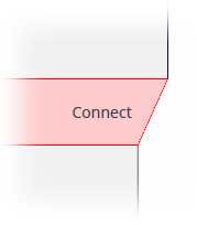
The edges of the fillet surfaces meet the start and/or end points of the boundaries exactly.
User Defined
![]()
(Interior only) Displays the flow setting used by Auto at each interior boundary of the input surface sets. The settings display as blue manipulators. Clicking the manipulator cycles through the applicable options. If Auto Update is turned on, that section of the fillet rebuilds using the new Interior Flow Control option.
 - Connect
 - Default
  - T-Align: Behaves similar to Edge Align when only one edge is available from either of the two input surfaces.
 - Relink: Displays when linked boundaries have been unlinked. When a linked interior edge is unlinked, Alias creates two interior boundaries. Click the Relink manipulator to merge the two interior edges.
  - Free: Appears when the result is a three-sided surface. In this case, one internal edge is considered a free edge.
See Specify Interior Flow Control options.
Modify Range
When this option is selected, Start and End sliders appear in the control window, and arrow manipulators appear on the selected fillets. Drag these arrows to modify the extent of the fillets across the input surfaces.
The Start or End of the range can only be modified if the flow control option for that end was set to Default.
Start/End
Use these sliders to modify the extent of the fillet. Start and End values of 0.0 and 1.0 respectively, define the original extent.
Fillet Structure
Surface Type
Multiple surfaces – Multiple surfaces, corresponding to the boundaries between the original surfaces, are created. (Extra spans are added if necessary, and subject to Max. Spans, to meet tangent or curvature requirements.) This gives you much lighter fillet surfaces and better continuity with the original surfaces.
Single surface – A single fillet surface is built.
If curves-on-surface are created at the edges of the fillets (see Trim Type option below) they are segmented to correspond to the multiple fillet surfaces.
Bézier Surfaces
This option only appears if Surface Type is set to Multiple surfaces. If it is checked on, each surface will be a Bézier patch.
Bézier patches have a single span, and their maximum degree in the U direction is set through the Explicit Control section. The default is degree 5.
Short Edge Tolerance
In the case of cross-knot insertion, the system will not allow spans to have a length smaller than this value.
Control Options
Trim Type
Automatic – Automatically trims the original surfaces back to the contact line.
Curves-on-surface– Creates curves on surface along the contact lines, allowing you to trim manually.
Off – Does not trim the original surfaces.
Auto Update
Automatically updates the fillet surface as you change options.
If your surface is very complex and takes a long time to update, turn this option off and click the Update button when you want to update the surface.
The  key can be used to interrupt lengthy surface fillet computations.
Curvature Comb
Displays a curvature comb plot across the resulting surface.
Inter Continuity
Checking on this option displays continuity locators between the output surfaces, indicating whether or not they are tangent continuous. Green T locators indicate that the surfaces are tangent continuous while red/yellow T locators indicate they are not.
The Continuity Angle fromPreferences > Construction Options is used when testing for tangent continuity, and a shared boundary is only checked if it doesn't present any gap larger than the Topology Distance tolerance (also found in Construction Options).
Only natural (non-trimmed) edges are checked.
Continuity Check
Checks the continuity between surface patches when multiple surfaces are created. This is particularly useful when you use the Bezier option to create single-span surfaces, as you will typically be working at the production quality level and so you'll want to watch out for and fix any small continuity errors.
Create Metadata
Specifies whether or not the Surface Fillet tool creates history metadata.
Buttons
Reset
Restores your saved settings. If you have not saved custom options, Reset restores the installed option settings.
Update
Updates the surface with the current settings when Auto Update is off.
Undo All
Reverses any effects of the tool.
Next
Resets the tool to begin a new surface.